Direction of rotation (5.4), Guarding (5.5), Priming and auxiliary supplies (5.6) – Flowserve CPX IDP User Manual
Page 21: Starting the pump (5.7), 3 open impeller clearance, 4 direction of rotation, 5 guarding, 6 priming and auxiliary supplies, 7 starting the pump
CPX, CPXR, CPXN and CPXP USER INSTRUCTIONS ENGLISH 71569117 09-11
Page 21 of 44
flowserve.com
5.3 Open impeller clearance
The impeller clearance is set in the factory. This may
require adjustment because of increase in liquid
temperature. If piping attachment cause the impeller
clearance to change, correct piping. For setting
instructions see section 6.7, Setting impeller
clearance.
5.4 Direction of rotation
Serious damage can result if the pump
is started or run in the wrong direction of rotation.
The pump is shipped with the coupling element
removed. Ensure the direction of rotation of the motor is
correct before fitting the coupling element. Direction of
rotation must correspond to the direction arrow.
If maintenance work has been carried
out to the site's electricity supply, the direction of
rotation should be re-checked as above in case the
supply phasing has been altered.
5.5 Guarding
Guarding is supplied fitted to the pump set. In
member countries of the EU and EFTA, it is a legal
requirement that fasteners for guards must remain
captive in the guard to comply with the Machinery
Directive 2006/42/EC. When releasing such guards,
the fasteners must be unscrewed in an appropriate
way to ensure that the fasteners remain captive.
Whenever guarding is removed or disturbed ensure
that all the protective guards are securely refitted
prior to start-up.
5.6 Priming and auxiliary supplies
5.6.1 CPX, CPXR and CPXN filling and priming
Ensure inlet pipe and pump casing is
completely full of liquid before starting continuous
duty operation.
Priming may be carried out with an ejector, vacuum
pump interceptor or other equipment, or by flooding
from the inlet source.
When in service, pumps using inlet pipes with foot
valves may be primed by passing liquid back from the
outlet pipe through the pump.
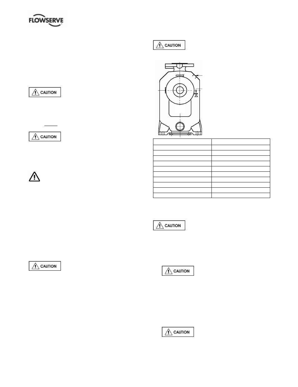
5.6.2 CPXP filling and self priming
Fill the pump with liquid to be pumped,
or compatible liquid, via the filling plug [6569.4],
before starting continuous duty operation.
Pump housing
filling hole.
When the initial fill
reaches the suction
pipe, excess liquid will
flow out of the casing.
Pump size
Initial fill litre (US gal.)
40-40CPXP125
2.5 (0.65)
80-80CPXP125
6.0 (1.50)
40-40CPXP160
3.0 (0.80)
80-80CPXP160
6.5 (1.75)
40-40CPXP200
5.0 (1.35)
65-65CPXP200
8.5 (2.25)
80-80CPXP250
12.0 (3.20)
100-100CPXP250
36.0 (9.50)
100-100CPXP315
14.8 (3.95)
150-150CPXP315
18.0 (4.80)
The pump has self-priming action for which a separate
air pump is not normally required.
5.6.3 Auxiliary supplies
Ensure all electrical, hydraulic,
pneumatic, sealant and lubrication systems (as
applicable) are connected and operational.
5.7 Starting the pump
5.7.1 Starting the CPX, CPXR and CPXN
a)
Ensure flushing and/or cooling/
heating liquid supplies are turned ON, before
starting pump.
b) CLOSE the outlet valve.
c) OPEN all inlet valves.
d) Prime the pump. Ensure the air has a route to
escape from the pump.
e) Start motor and check the outlet pressure.
f) If the pressure is satisfactory, SLOWLY open the
outlet valve.
g)
Do not run the pump against a
closed valve for more than 10 seconds.