11 sealing arrangements, Sealing arrangements (6.11) – Flowserve CPX IDP User Manual
Page 31
CPX, CPXR, CPXN and CPXP USER INSTRUCTIONS ENGLISH 71569117 09-11
Page 31 of 44
flowserve.com
6.10.4 Impeller assembly and setting
6.10.4.1
Impeller assembly and setting
a) Fit a new O-ring [4610.1] into the impeller [2200]
using a small amount of grease to hold it in place.
Apply anti-galling compound (which does not
contain copper) to the impeller thread to help
subsequent removal.
b) Assemble impeller onto the shaft.
c) Tighten the impeller. Use the same method as in
disassembly but rotating in opposite direction. A
few sharp strikes will tighten it to the correct level.
6.10.4.2
Impeller assembly with key drive impeller
a) Fit a new impeller sealing gasket [4590.4] against
shaft shoulder.
b) Fit impeller key [6700.2].
c) Assemble impeller onto the shaft.
d) Fit a new O-ring [4610.5] into the impeller nut
[2912.1/2912.2] groove.
e) Apply anti-galling compound (which does not
contain copper) to the impeller nut threads to help
any subsequent removal.
f) Fit impeller nut onto the shaft [2100] and torque
up.
6.10.5 Assembly of bearing housing into casing
a) Fit a new gasket [4590] into the casing [1100].
On the CPXR a new gasket is required
each side of the distance ring [2510.2].
b) Install the bearing housing assembly into the
pump casing. Coat the screws [6570.1] with anti-
galling compound and tighten into casing.
c) Check impeller front clearance against original
setting or process requirement and adjust as
necessary. (See section 6.7, Setting impeller
clearance.)
d) Ensure that all other items have been re-attached
and all fasteners tightened, then follow the
instructions in the sections on Installation and
Commissioning.
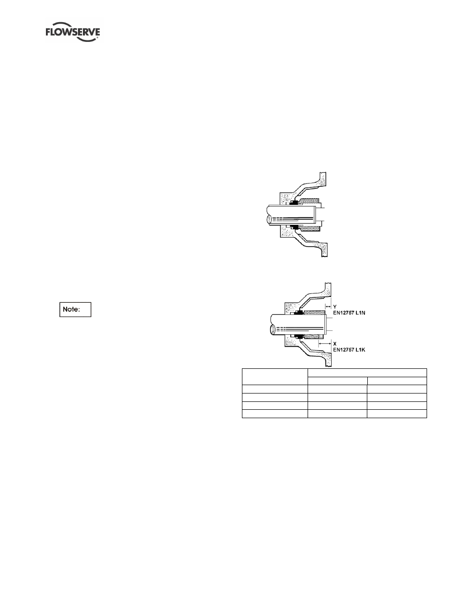
6.11 Sealing arrangements
The following section shows details of the seal
arrangements. The dimensions provided are for non-
step balanced mechanical seals conforming to EN
12757 L1K and L1N. Contact your nearest Flowserve
sales office or service centre if you require further
information, such as a mechanical seal dimensional
drawing, or are unsure of the specific arrangement
supplied. Refer also to section 4.6.5, Auxiliary piping.
6.11.1 Single seal types
6.11.1.1
Single stepped balanced seal
6.11.1.2
Single unbalanced (or inherently
balanced) seal
Bearing housing
Setting dimension (mm)
X
Y
Frame 1
23.5
11.0
Frame 2
34.0
19.0
Frame 3
33.5
11.0
Frame 4
51.5
24.0