Clearances, impeller (6.7), Fastener torques (6.6), Setting impeller clearance (6.7) – Flowserve CPX IDP User Manual
Page 26: Tools required (6.5), Torques for fasteners (6.6), 4 recommended spares, 5 tools required, 6 fastener torques, 7 setting impeller clearance
CPX, CPXR, CPXN and CPXP USER INSTRUCTIONS ENGLISH 71569117 09-11
Page 26 of 44
flowserve.com
6.4 Recommended spares
For two years operation (as per VDMA 24296).
Part no. Designation
Number of pumps
(including stand-by)
2
3
4
5
6/7
8/9
10(+)
2200
Impeller
1
2
3
30%
2100
Shaft
1
2
3
30%
3712.1 Bearing locknut
1
2
3
4
50%
2400
Sleeve (if fitted)
2
3
4
50%
3011
Radial ball bearing
1
2
3
4
50%
3013
Thrust bearing
1
2
3
4
50%
4590.1 * Gasket
4
6
8
9
12
150%
4610.1 O-ring
4
6
8
9
12
150%
4610.2 O-ring
4
6
8
9
10
100%
2540.2 Deflector
1
2
3
30%
4130
Gland packing
2
3
4
40%
4134
Lantern ring
1
2
3
30%
4200
Mechanical seals
1
2
3
30%
-
Power end
-
-
-
-
-
1
2
* Note: for CPXR replace with the following part:
4590.1 Gasket
8 12
16
18
24
300%
Additional spares for keyed impeller option
2912.1 /
2912.2
Impeller nut
1
2
3
30%
4610.4
O-ring
(if sleeve fitted)
2
3
4
50%
4610.5 O-ring
4
6
8
9
12
150%
6700.2 Key
1
2
3
30%
6.5 Tools required
A typical range of tools that will be required to
maintain these pumps is listed below.
Readily available in standard tool kits, and dependent
on pump size:
Open ended spanners (wrenches) to suit up to
M 24 screws/nuts
Socket spanners (wrenches), up to M 24 screws
Allen keys, up to 10 mm (A/F)
Range of screwdrivers
Soft mallet
More specialized equipment:
Bearing pullers
Bearing induction heater
Dial test indicator
C-spanner (wrench) - for removing shaft nut.
(If difficulties in sourcing are encountered, consult
Flowserve.)
Coupling grip/shaft spanner
6.6 Fastener torques
Fastener
Screw size
Torque Nm (lbf
•ft)
All except where
otherwise stated
M8
M10
M12
M16
M20
16 (12)
25 (18)
35 (26)
80 (59)
130 (96)
Impeller nut
M12
M16
M22
M24
16 (12)
41 (31)
106 (79)
135 (100)
Non-metallic gaskets incur creep
relaxation - before commissioning the pump check
and retighten fasteners to tightening torques stated.
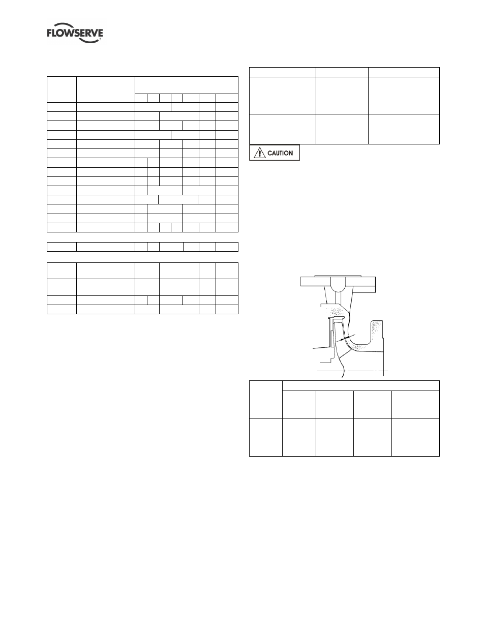
6.7 Setting impeller clearance
This procedure may be required after the pump has
been dismantled or a different clearance is required.
Before carrying out this procedure ensure that the
mechanical seal(s) [4200] fitted can tolerate a change
in their axial setting, otherwise it will be necessary to
dismantle the unit and reset the seal axial position
after adjusting the impeller clearance.
Temp
ºC
(ºF)
Clearance mm (in.)
Impellers
up to
210 mm
Impellers
211 mm to
260 mm
Impellers
over 260 mm
(except *)
(*)150CPX400
(*)200CPX400
(*)150CPX500
50 (122)
100 (212)
150 (302)
200 (392)
250 (482)
0.3 (0.012)
0.4 (0.016)
0.5 (0.020)
0.6 (0.024)
0.7 (0.028)
0.4 (0.016)
0.5 (0.020)
0.6 (0.024)
0.7 (0.028)
0.8 (0.032)
0.5 (0.020)
0.6 (0.024)
0.7 (0.028)
0.8 (0.032)
0.9 (0.036)
1.0 (0.040)
1.0 (0.040)
1.1 (0.044)
1.2 (0.048)
1.3 (0.052)
a) Disconnect the coupling if it has limited axial
flexibility.
b) Record the gap between the bearing carrier [3240]
and bearing housing [3200] using feeler gauges.
c) Loosen the bearing carrier screws [6570.2] and
back off the bearing carrier 2 mm (0.08 in.) using
the jacking screws [6570.3].