8 disassembly, Disassembly (6.8), Dismantling (6.8, disassembly) – Flowserve CPX IDP User Manual
Page 27
CPX, CPXR, CPXN and CPXP USER INSTRUCTIONS ENGLISH 71569117 09-11
Page 27 of 44
flowserve.com
For CPX, CPXN and CPXP
d) Tighten the bearing carrier screws [6570.2] evenly,
drawing the bearing carrier towards the bearing
housing, until the impeller [2200] contacts the pump
casing. [1100] Turn the shaft [2100], during this
procedure, until a detectable rub is obtained. This
is the zero clearance position.
e) Set a dial indicator to zero on the shaft end or
measure the bearing carrier to bearing housing
gap and record the measurement.
f) Slacken the bearing carrier screws [6570.2].
g) Tighten jacking screws [6570.3] evenly (about
one flat at a time) until the dial indicator or feeler
gauge shows the correct impeller clearance from
the zero clearance position. This clearance
should be between 0.3 and 2 mm (0.008 and
0.080 in.) depending on the nature of the pumped
fluid. (See table above.)
h) Evenly tighten the bearing carrier screws [6570.2]
keeping the dial indicator or feeler gauges reading
the correct setting. Then tighten the hex nuts
[6580.1] to lock the jacking screws in position.
For CPXR only
The impeller does not have a fine front
clearance setting and adjustment of the impeller
is not normally required.
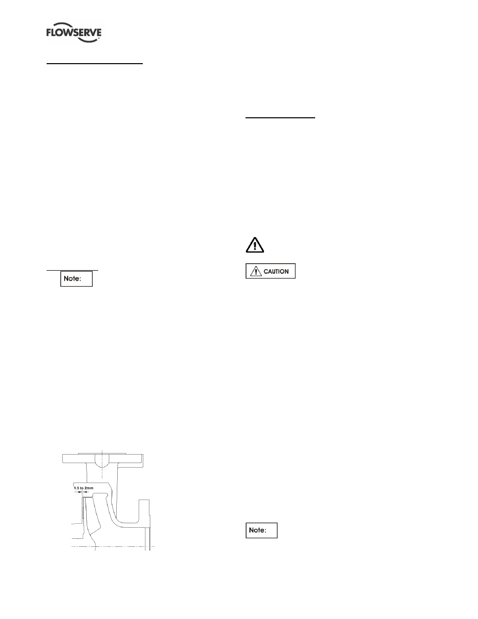
d) Tighten the jacking screws [6570.3] evenly, pushing
the bearing carrier away from the bearing housing,
until the impeller [2200] contacts the cover. [1220]
Turn the shaft [2100], during this procedure, until a
detectable rub is obtained. This is the zero
clearance position.
e) Set a dial indicator to zero on the shaft end or
measure the bearing carrier to bearing housing
gap and record the measurement.
f) Slacken the jacking screws [6570.3].
g) Tighten bearing carrier screws [6570.2] evenly
(about one flat at a time) until the dial indicator or
feeler gauge shows the correct impeller
clearance from the zero clearance position. This
clearance should be 1.5 - 2 mm (0.06 - 0.08 in.)
(See drawing.)
h) Tighten the jacking screws [6570.3] until they
contact the bearing carrier, keeping the dial
indicator or feeler gauges reading the correct
setting. Then tighten the hex nuts [6580.1] to
lock the jacking screws in position.
For all pump types
i)
Compare the original and final gaps between the
bearing carrier and bearing housing to check if
the movement of the shaft has exceeded the seal
capability (over/under compression of seal).
Re-position the seal to correct this.
j)
Check that the shaft [2100] can turn freely without
binding.
k) If a cartridge seal [4200] is fitted it should be
reset at this point.
l)
Ensure the coupling distance between shaft ends
(DBSE) is correct. Reset/re-align if necessary.
6.8 Disassembly
Refer to Safety section before dismantling the
pump.
Before dismantling the pump for
overhaul, ensure genuine Flowserve replacement
parts are available.
Refer to sectional drawings for part numbers and
identification. See section 8, Parts lists and drawings.
6.8.1 Bearing housing
To remove, proceed as follows:
a) Disconnect all auxiliary pipes and tubes where
applicable.
b) Remove coupling guard and disconnect coupling.
c) If oil lubricated frame, drain oil by removing drain
plug [6569.3].
d) Record the gap between the bearing carrier and
bearing housing so that this setting can be used
during workshop assembly.
e) Place hoist sling through bearing housing window.
f) Remove casing screws [6570.1] and support foot
[3134] to baseplate screws.
g) Remove bearing housing assembly from pump
casing [1100]. The two threaded holes in the
bearing housing flange can be used for jacking
screws to assist with removal.
h) Remove pump casing gasket [4590.1] and
discard. A replacement gasket will be required
for assembly.
i)
Clean gasket mating surfaces.
On CPXP diffuser casing sizes it is not
normally necessary to remove the diffuser [1410,
4590.2 and 6570.5].