4 performance and operating limits, 4 installation, 1 location – Flowserve LR Worthington User Manual
Page 12: 2 part assemblies, 3 foundation
LR, LRV, LLR and LR-S USER INSTRUCTIONS ENGLISH 71569088 08-10
Page 12 of 48
flowserve.com
3.3.9 Accessories
Accessories may be fitted when specified by the
customer.
3.4 Performance and operating limits
This product has been selected to meet the
specifications of your purchase order, see section 1.5.
The following data is included as additional information to
help with your installation. It is typical, and factors such
as temperature, materials, and seal type may influence
this data. If required, a definitive statement for your
particular application can be obtained from Flowserve.
3.4.1 Operating limits
Pumped liquid temperature limits *
-20 to +150 ºC
(-4 to +302 ºF)
Maximum ambient temperature *
-20 to +40 ºC
(-4 to +104 ºF)
Maximum soft solids in suspension *
up to 3 % by volume
(refer for size limits)
Maximum pump speed
refer to the nameplate
* Subject to written agreement from Flowserve.
4 INSTALLATION
Equipment operated in hazardous locations
must comply with the relevant explosion protection
regulations. See section 1.6.4, Products used in
potentially explosive atmospheres.
4.1 Location
The pump should be located to allow room for
access, ventilation, maintenance and inspection with
ample headroom for lifting and should be as close as
practicable to the supply of liquid to be pumped.
Refer to the general arrangement drawing for the
pump set.
4.2 Part assemblies
Motors may be supplied loose on LRV pumps,
typically on frame sizes 250 and above. It is the
responsibility of the installer to ensure that the motor
is assembled to the pump and lined up as detailed in
section 4.5.2.
4.3 Foundation
There are many methods of installing
pump units to their foundations. The correct method
depends on the size of the pump unit, its location and
noise vibration limitations. Non-compliance with the
provision of correct foundation and installation may
lead to failure of the pump and, as such, would be
outside the terms of the warranty.
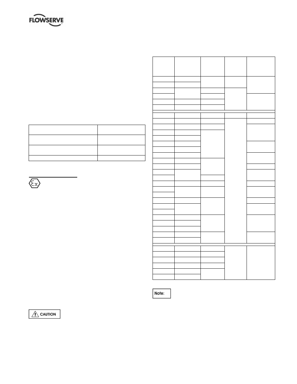
3.4.2 Pump and impeller data
Pump
size
Impeller
minimum
passage size
mm (in.)
Nominal
wear ring
diameter
mm (in.)
Mean radial
wear ring
clearance
mm (in.) *
Approx. oil
capacity, both
bearings
litres (fl. oz.)
1.5LLR-7
6 (0.24)
95.25 (3.75) 0.19 (0.007)
0.16 (5.4)
1.5LLR-10
9 (0.35)
2LLR-9
7.5 (0.29)
103.2 (4.06)
0.22 (0.009)
2LLR-11
124.0 (4.88)
0.19 (6.4)
3LLR-11
10.5 (0.41)
139.9 (5.51)
4LLR-11
17 (0.67)
157.3 (6.19)
2.5LR10
9 (0.35)
95.25 (3.75) 0.19 (0.007)
0.16 (5.4)
2.5LR-13
13 (0.51)
123.8 (4.88)
0.22 (0.009)
0.17 (5.8)
3LR-9
8 (0.31)
103.2 (4.06)
0.16 (5.4)
3LR-12
14.5 (0.57)
123.8 (4.88)
4LR-10
16.5 (0.65)
4LR-11
18 (0.71)
0.17 (5.8)
4LR-12
12 (0.47)
4LR-14
16 (0.63)
0.16 (5.4)
5LR-10
16.5 (0.65)
139.7 (5.5)
5LR-13
15 (0.59)
0.17 (5.8)
5LR-15
17 (0.67)
0.19 (6.4)
5LR-19
168.4 (6.63)
6LR-10
21 (0.83)
157.2 (6.19)
0.16 (5.4)
6LR-13
17.5 (0.69)
157.2 (6.19)
0.19 (6.4)
6LR-16
6LR-18
23.5 (0.93)
190.5 (7.5)
0.21 (7.1)
8LR-12
22 (0.87)
0.19 (6.4)
8LR-14
8LR-20
27 (1.06)
228.6 (9.0)
0.21 (7.1)
10LR-14
44.5 (1.75)
10LR-16
39 (1.54)
10LR-17
41 (1.61)
278 (10.95)
0.28 (9.46)
10LR-18
22 (0.87)
6LR-18S
26.5 (1.04)
215.9 (8.5)
0.13 (0.005)
0.47 (15.9)
8LR-18S
38 (1.50)
247.7 (9.75)
8LR-23S
23 (0.91)
235 (9.25)
10LR-14S
42.5 (1.67)
247.7 (9.75)
10LR-18S
57.5 (2.26)
273.1 (10.75)
12LR-14S
58.5 (2.30)
* May be up to 0.13 mm (0.005 in.) larger if casing ring and
impeller have a tendency to gall.
Clearances for non-metallic wear rings are
smaller, typically 50 - 65% of those for the standard
metallic rings shown above.