Flowserve LR Worthington User Manual
Page 27
LR, LRV, LLR and LR-S USER INSTRUCTIONS ENGLISH 71569088 08-10
Page 27 of 48
flowserve.com
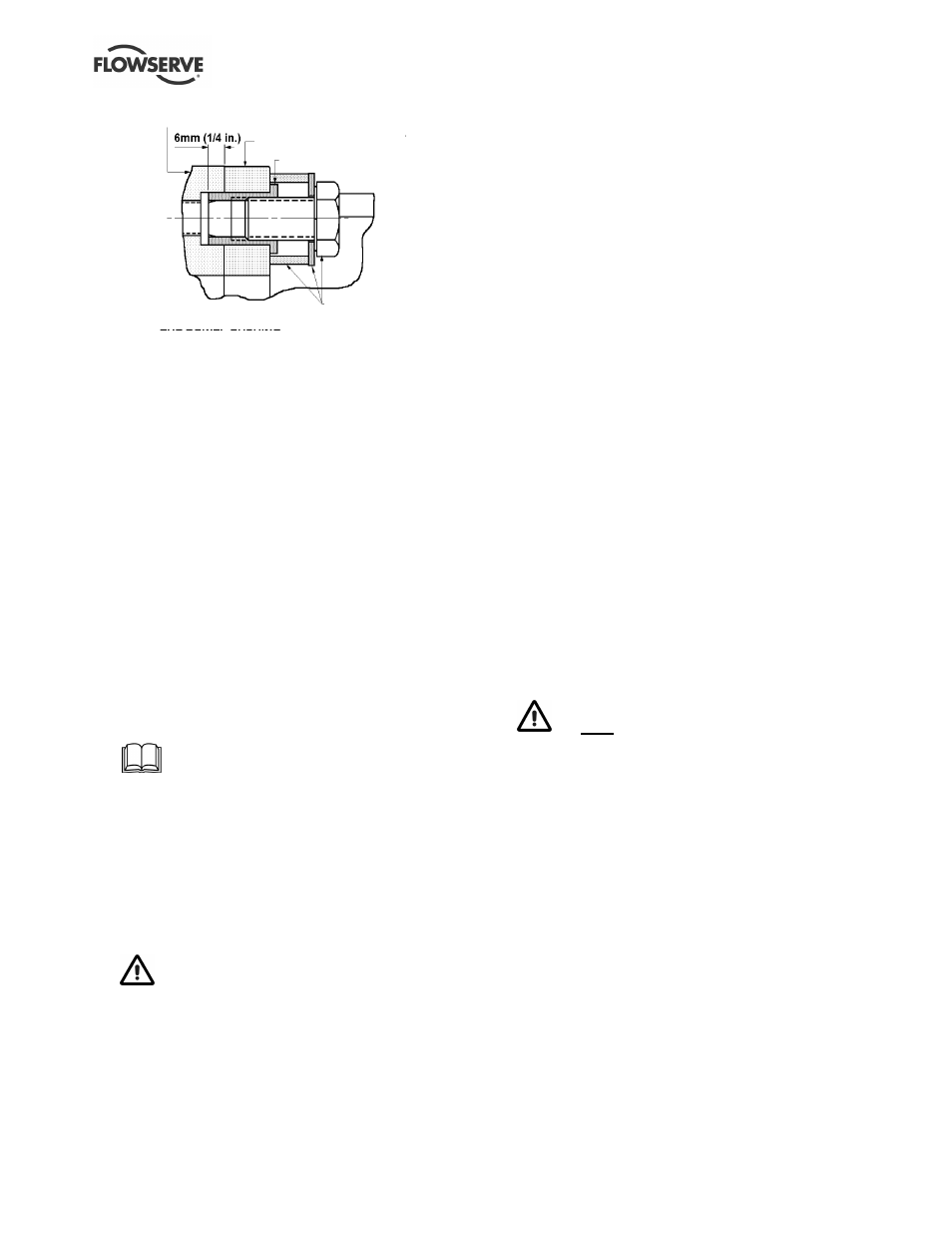
L o w e r h a l f c a s i n g
B e a r i n g h o u s i n g
D o w e l b u s h
P u l l e r
p a r t s
l)
Lift out rotor assembly. Use care in slinging,
handling and supporting of the rotor for
subsequent dismantling. Place rotor securely on
two support blocks.
m) When removing the rotor assembly, the casing
wear rings [1500] will be attached to it. They are
fixed by two diametrically opposite grubscrews
[6814.1] inserted into the casing ring and located in
grooves in the lower half casing. (On the LLR
design the interstage bush [1610] between the two
impellers will also be attached to the shaft.)
n) Remove bearing covers and slide bearing housing
off the bearings. Some pump sizes have a shim
fitted at the non-drive end – retain for future use.
o) Release the bearing lockwasher [6541] at the non-
drive end and remove the bearing nut [3712]. Pull
off both ball bearings using a suitable puller,
ensuring force is applied to inner race only. Retain
the non-drive end bearing disc spacer [3645], fitted
to the shaft [2100] on some pump sizes, for future
use. Remove the bearing covers [3260].
p) Depending on configuration remove glands/seal
covers, packing and lantern ring/mechanical seal.
Refer to any special instructions supplied
with the mechanical seal.
q) Remove the two socket head grub screws [6814.2]
securing each shaft nut [2910.1]. Using C-spanner
remove shaft nuts. Slide off shaft sleeves [2450].
r) Remove impeller(s), casing wear rings, impeller
key, and interstage bush, if fitted. The 2.5LR10 and
2.5LR13 are not fitted with shaft sleeves and
removal of the impeller nut will allow the impeller to
be withdrawn.
If impellers prove difficult to remove, the use
of heat is permissible. Refer to Section 1.6, Safety,
Applying heat to remove impeller, for more details.
s) If impeller wear rings [2300] are also fitted, they
are shrunk onto the impeller and fixed with
locking grub screws [6814.4] between their
diametral mating surfaces.
t)
To remove the impeller wear rings, remove the
locking grub screws and heat up the wear ring until
it slides off easily.
6.8.2 LR-S
a) Isolate motor and lock off electrical supply in
accordance with local regulations.
b) Isolate suction and discharge valves.
c) Remove coupling guards and disconnect the
coupling halves.
d) Drain pump casing. Remove any auxiliary piping
if applicable.
e) If bearings are oil lubricated drain oil from both
bearing housings [3200].
f) Remove the pump half coupling.
g) Unbolt the glands/seal covers from the casing.
If glands are split type, remove completely.
h) With a suitable punch, drive out the two straight
roll pins which are used on the horizontal split
flange to align the upper and lower half casings
[1214 and 1213].
i)
Remove the screws [6569.4] that hold the upper
and lower half of the casing together and remove
the upper half. Tapped holes are provided in the
joint flange to enable the use of forcing screws to
loosen the joint.
j)
Lift the casing upper half using the cast on lifting
lugs where provided. Where there are no integral
lifting lugs, remove the pipe plug or fittings, if
used, from the volute vent connection located on
top of the casing upper half and install a special
steel lifting eye with a threaded shank to match
the pipe tap opening in the casing.
Do NOT use these methods to lift the
bottom half or complete pump casing.
k) Remove the bearing housing to casing bolts and
dowels on each side.
l)
Lift out rotor assembly. Use care in slinging,
handling, and supporting of the rotor for
subsequent dismantling.
m) Place rotor securely on two support blocks.