5 tools required, 6 fastener torques, 7 renewal clearances – Flowserve LR Worthington User Manual
Page 26: 8 disassembly
LR, LRV, LLR and LR-S USER INSTRUCTIONS ENGLISH 71569088 08-10
Page 26 of 48
flowserve.com
6.5 Tools required
A typical range of tools that will be required to
maintain these pumps is listed below.
Readily available in standard tool kits, and dependent
on pump size:
•
Open ended spanners (wrenches) to suit up to
M 24 (
7
/
8
in.) screws/nuts
•
Socket spanners (wrenches), up to M 24 (
7
/
8
in.)
screws
•
Allen keys, up to 6 mm (¼ in.) A/F
•
Range of screwdrivers
•
Soft mallet
More specialized equipment:
•
Bearing pullers
•
Bearing induction heater
•
Dial test indicator
•
C-spanner (wrench) - for removing shaft nut.
(Consult Flowserve if this is difficult to source.)
See also section 6.8.1.k.
6.6 Fastener torques
Screw/bolt size
Torque Nm (lbf·ft)
Pump feet
fasteners
All other
fasteners
M8 (
5
/
16
in.)
M10 (
⅜
in.)
M12 (½ in.)
M16 (
⅝
in.)
M20 (¾ in.)
M24 (
⅞
in.)
-
-
63 (46)
170 (125)
340 (250)
590 (435)
10 (7)
20 (15)
34 (25)
84 (62)
165 (120)
285 (210)
Non-metallic gaskets incur creep
relaxation - before commissioning the pump check
and retighten fasteners to tightening torques stated.
6.7 Renewal clearances
As wear takes place between the impeller and casing
wear ring the overall efficiency of the pump set will
decrease. To maintain optimum efficiency it is
recommended that rings are replaced and the impeller
renovated when the radial clearance detailed in section
3.4.2 has doubled. On the LRV it is recommended that
the product lubricated bearing is renewed at a
diametrical clearance of 0.5 mm (0.02 in.).
6.8 Disassembly
Refer to section 1.6, Safety, before dismantling
the pump.
Before dismantling the pump for
overhaul, ensure genuine Flowserve replacement
parts are available.
To dismantle the pump consult the sectional
drawings. See section 8, Parts lists and drawings.
6.8.1 LR and LLR
a) Isolate motor and lock off electrical supply in
accordance with local regulations.
b) Isolate suction and discharge valves.
c) Remove coupling guards and disconnect the
coupling halves.
d) Drain pump casing. Remove any auxiliary piping
if applicable.
e) If bearings are oil lubricated drain oil from both
bearing housings [3200].
f) Remove the pump half coupling.
g) Unbolt the glands/seal covers from the casing.
If glands are split type, remove completely.
h) With a suitable punch, drive out the two straight
roll pins which are used on the horizontal split
flange to align the upper and lower half casings
[1214 and 1213].
i)
Remove the screws, which hold the upper and
lower half of the casing together, and remove the
upper half. Tapped holes are provided in the joint
flange to enable the use of forcing bolts to loosen
the joint.
j)
Lift the casing upper half using the cast on lifting
lugs where provided. Where there are no integral
lifting lugs, remove the pipe plug or fittings, if used,
from the volute vent connection located on top of
the casing upper half and install a special steel
lifting eye with a threaded shank to match the pipe
tap opening in the casing.
Do NOT use these methods to lift the
bottom half or complete pump casing.
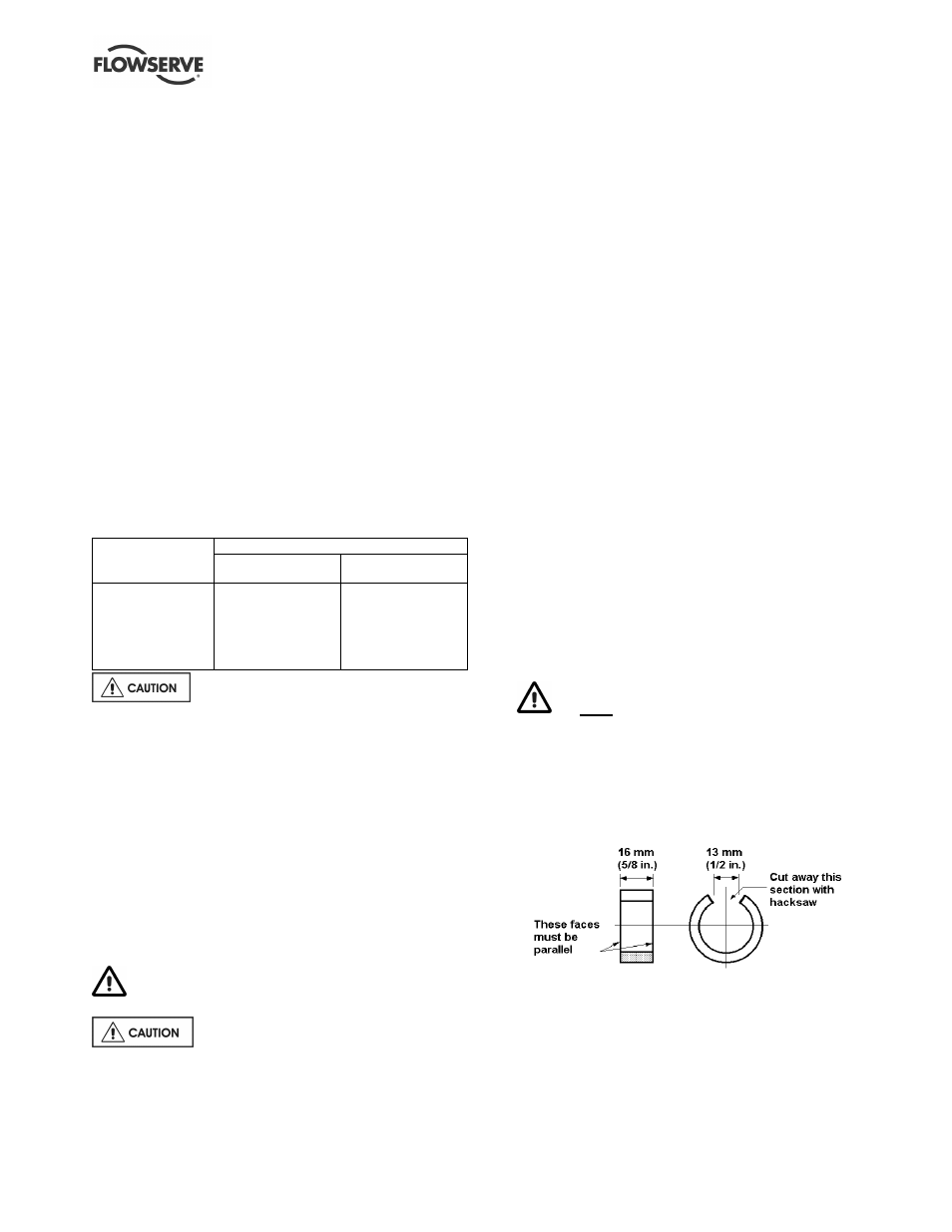
k) Remove the bearing housing to casing screws
[6570.1] and remove the 2 dowel bushings on
each side. A tool for removing the bushings can
be easily and economically made as shown in the
following diagrams:
Material: 25 mm (1 in.) standard weight steel pipe