Flowserve LR Worthington User Manual
Page 30
LR, LRV, LLR and LR-S USER INSTRUCTIONS ENGLISH 71569088 08-10
Page 30 of 48
flowserve.com
d) Fit the two shaft sleeves, O-rings and shaft nuts and
lightly secure the impeller(s) on the shaft. Take care
to protect the sleeve O-rings from damage on the
shaft threads. The sleeves and nuts define the
impeller position on the pump shaft and hence in
the pump casing. Initially position the impeller(s)
centrally on its keyway. This position may be
adjusted slightly later on in the assembly process.
2.5LR pumps do not have sleeves fitted
and the impeller is positively held against the shaft
shoulder by the impeller nut and cannot
subsequently be adjusted.
e) It is recommended that gasket sealing compound
Loctite 574 or equivalent is used between sleeve
and impeller mating faces to protect the shaft
from the liquid pumped.
f) When mechanical seals are fitted the rotating parts
can be slid onto the sleeves before the sleeves are
fitted onto the shaft. The seal retaining rings should
be left loose. On some sizes of LLR a second
stage stuffing throttling box bush [1630] is fitted, this
must be slid onto the shaft before the seal.
Refer to any special instructions supplied
with the mechanical seal.
g) If gland packing is used fit stuffing box throttling
bush and glands.
h) Fit mechanical seal covers complete with seal
seat, liquid flingers [2540] and bearing covers
complete with gaskets.
i)
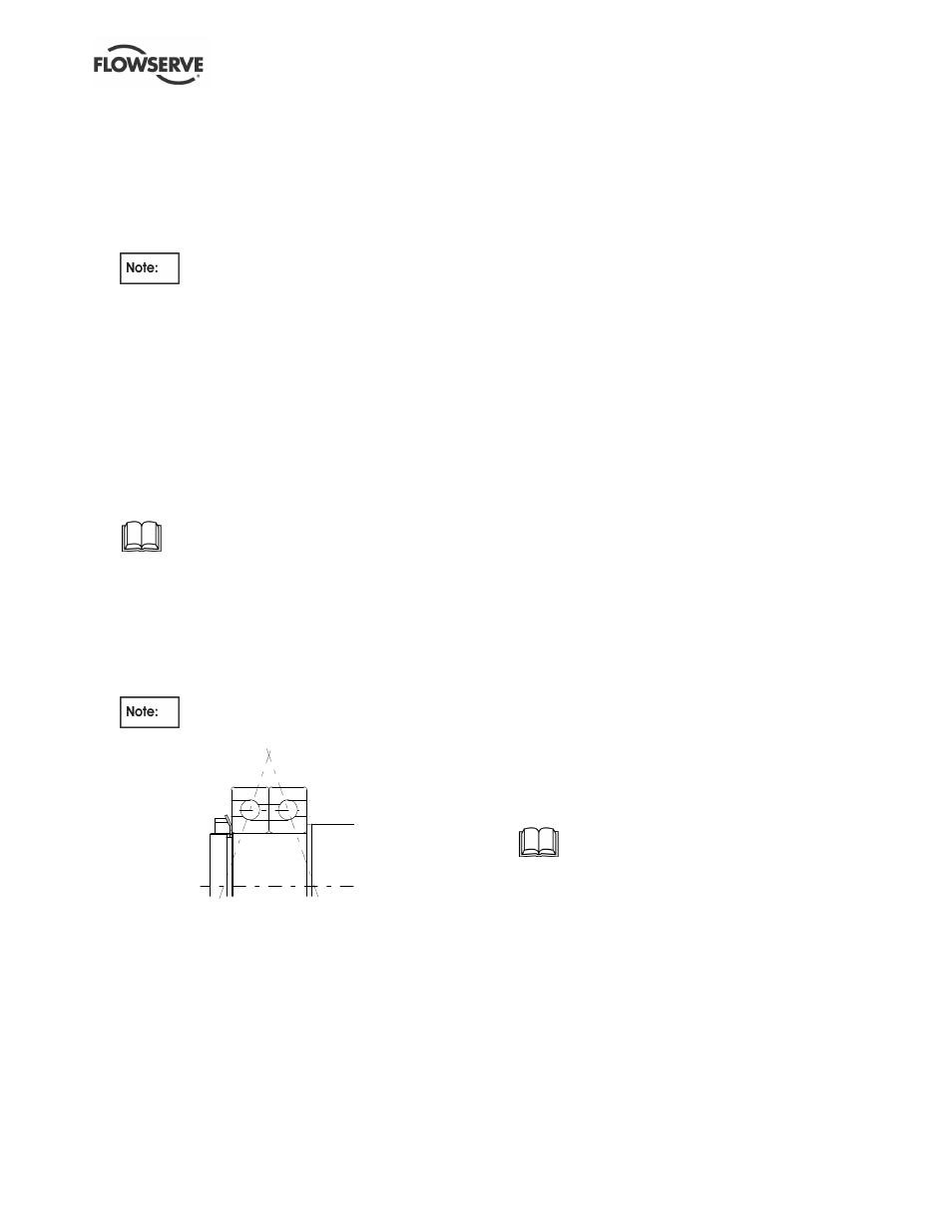
Fit the bearings onto the shaft. The main thrust
bearing is at the non-drive end.
Where double row bearings are fitted
these must be assembled 'back to back' as below:
The 2.5LR13, 4LR11, 4LR14 and 5LR13 pumps
have bearing disc spacers fitted to the shaft at the
non-drive end. Ensure this is fitted before the
bearing is assembled to the shaft. The bearings
must be heated up to 100 ºC (212 ºF) using a hot
plate, oil bath or induction heater and slid onto the
shaft. Ensure bearing is fully seated against the
shaft shoulder and bearing disc spacer, where fitted.
j)
If grease lubricated, fill both sides of bearing with
grease.
k) Fit the bearing lockwasher and tighten the
bearing nut.
l)
Bend over a tab of lockwasher into bearing nut slot.
m) Slip casing wear rings, complete with anti-rotation
grub screws, loosely over the impeller hubs.
n) Slide the bearing housings over the bearings. All
pumps except the 10LR17 and 10LR18 have a
shim fitted between the outside diameter of the
non-drive end bearing and the bearing housing.
Ensure shim is seated against the shoulder in the
bearing housing before sliding housing over the
bearing. Ensure bearings are located square in
the housing bore.
o) If grease lubricated, one third fill the space
between bearing cover and bearing with grease.
Secure bearing cover, complete with gasket.
p) Fit the coupling hub.
6.10.1.4 Casing lower half
a) Coat the bearing housing to casing face with
liquid sealant to protect against corrosion.
b) Place the complete rotating assembly into the
casing ensuring that wear rings are in the correct
position and the anti-rotation grub screws are
located in the slots on the horizontal flange. If
working on an LLR pump the anti-rotation grub
screw in the second stage stuffing box bush,
when fitted, and the interstage bush must also
locate in the slot on the horizontal flange.
c) Locate the dowel bush within the holes in the
lower half casing and bolt the bearing housings to
the casing. The dowel bushes must be sprayed
with anti-seize compound (Molyslip or equivalent)
before assembly in to the housing/casing.
d) Torque up the fixing screws.
e) Check rotor for free rotation.
f) Centralize the impeller(s) within the casing
waterway by adjusting the shaft nut, if necessary.
Using a C-spanner fully tighten the shaft nuts and
lock with the two radial socket head grub screws.
g) Set the mechanical seals, if fitted, to correct working
length and tighten seal retaining ring screws.
Refer to any special instructions supplied
with the mechanical seal.
h) Check for free rotation.
6.10.1.5 Casing upper half
a) Lower the casing upper half over the lower half.
Take care to ensure the wear rings are correctly
located in the upper half bores.
b) Drive home the two casing roll pins to accurately
position the casing and torque up all horizontal
flange screws.
c) Check for free rotation.
d) Using a sharp flexible-bladed knife, cut off the
exposed casing gasket in the stuffing box area
flush with the stuffing box face.