Flowserve LR Worthington User Manual
Page 31
LR, LRV, LLR and LR-S USER INSTRUCTIONS ENGLISH 71569088 08-10
Page 31 of 48
flowserve.com
e) If mechanical seals are fitted apply a small
amount of silicon rubber sealant along the
horizontal joint line on the stuffing box face and fit
seal cover complete with gasket or O-ring. Take
care not to damage O-ring, if fitted, and locate
cover squarely on stuffing box face. Some seal
covers do not have a spigot location in the casing
bore and care must be taken to ensure the seal
seat bore is concentric to the shaft sleeve. This
is best achieved using feeler gauges between the
stationary seal seat bore and the shaft sleeve.
f)
Torque up seal cover screws and check shaft/
sleeve does not rub on seal cover or stationary seal
seat bore. Ensure any spare holes in mechanical
seal cover, particularly on cartridge mechanical
seals, have sealing plugs fitted.
g) If gland packing is fitted pack the gland, ensuring
that the cut ends in each ring are staggered by
120 degrees. The glands are packed as shown
on the relevant drawings in Sections 8.1 to 8.3.
Finger tighten the gland nuts.
h) Check coupling alignment, fit coupling drive
element(s) and fit guards.
i)
Pipe up any external auxiliary connections.
j)
Check for free rotation.
6.10.2 LR-S
6.10.2.1 Impeller wear rings
a) Impeller rings (when fitted) should be heated up
to approximately 100 ºC (212 ºF) using a hotplate
or hot oil bath and then slipped onto the impeller
and pressed down to the shoulder. (Do NOT use
a steel hammer to knock them into position.)
b) Drill and tap 3 holes approximately 120 degrees
apart into the diametral mating faces of the ring
and impeller and insert socket head grub screws.
(The existing half tapped holes from the removed
impeller ring cannot be re-used.)
6.10.2.2 Pre-assembly of casing gasket
a) Fit casing gasket to the bottom half horizontal
flange using a small amount of contact adhesive to
prevent movement when the top half is fitted. Do
not apply adhesive to the top surface of the gasket.
b) It is important that the external corner of the
casing gasket face and the stuffing box face is as
sharp as possible.
Do not chamfer with a file.
c) If necessary trim gasket to match volute profile.
Do not trim to stuffing box face at this stage.
6.10.2.3 Rotating element and bearing housing
a) Ensure all gaskets and O-rings are renewed and
replaced in the correct position during assembly.
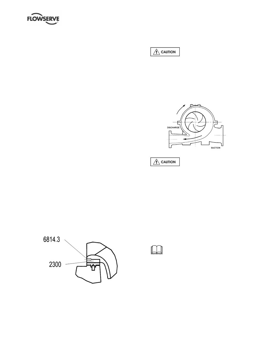
b) Assemble the impeller on the shaft. It is
important to mount the impeller so that the vane
tips point away from the apparent flow direction.
The rotor always rotates towards the expanding
section of the volute.
c)
The impeller is an interference fit on
the shaft and the impeller boss needs quickly
heating up to allow it to be fitted to the shaft. Take
extreme care when handling hot components.
Position impeller centrally on its keyway.
d) Fit the two shaft sleeves, O-rings and shaft nuts.
Take care to protect the sleeve O-rings from
damage on the shaft threads.
e) It is recommended that gasket sealing compound
Loctite 574 or equivalent is used between sleeve
and impeller mating faces to protect the shaft
from the liquid pumped.
f) When mechanical seals are fitted the rotating parts
can be slid onto the sleeves before the sleeves are
fitted onto the shaft. The seal retaining ring should
be left loose.
Refer to any special instructions supplied
with the mechanical seal.
g) If gland packing is used fit stuffing box throttling
bush [1630] and glands.
h) Fit mechanical seal covers complete with seal
seat, liquid flingers [2540] and bearing housings
complete with shaft seal rings.
i)
Fit the bearings on to the shaft. The main thrust
bearing is at the non-drive end. The bearings
must be heated up to 100 ºC (212 ºF) using a hot
plate, oil bath or induction heater and slid onto
the shaft. Ensure bearing is fully seated against
the shaft shoulder.