Flowserve VF User Manual
Page 15
VF USER INSTRUCTIONS ENGLISH 71561233 - 11/09
Page 15 de 32
If the pump is set on a tank, make sure that the
connection flange is perfectly flat and horizontal. If
the assembling is on a concrete stone or a metallic
structure, be sure of the flatness and rigidity of the
unit.
If the pump is mounted on a recently sunk well, the
soil round the well may not be stabilized. After
some times, check perpendicularity and level, and
if needed, adjust before definitive anchoring.
The anchoring frame will then be fixed
provisionally.
Anchor bolts must be appropriate for the foot bolt
holes. Use anchor bolts of accepted standards and
sufficient length so that they may be clamped
safely in the grout.
NF E 27 811
Provide sufficient space in the foundation to
accommodate the anchor bolts. If necessary,
provide concrete gullets.
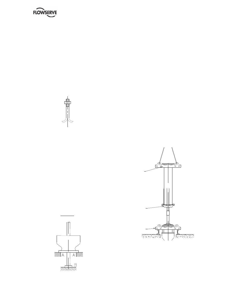
4.2.1 Installation of the pump
4.2.1.1 Erection of hydraulic unit
a) Install the pump in the position defined in
figure 1.
b) The last body, fitted with its wear ring and its
bearing liner, shall be help upside down on the
shims in AA.
c) Protect the shaft on the entire bearing area
which subsequently receives the jacket, into
the body. Wedge in B so as to place the shaft
in its final position in the body.
d) Engage the shaft, fitted with its last jacket, into
the body. Wedge in B so as to place the shaft
in its final position in the body.
FIGURE I
e) As assembly proceeds, coat the assembly
faces with a sealing product.
f) All impellers and jackets (and wells) shall be
locked onto the shaft by means of the nut and
its lock-crew provided for this purpose.
g) Tighten the assembly.
h) Attach then the suction ear.
i)
Place the pump in vertical position, resting
onto its ear, and complete the assembly by
attaching the discharge cuff.
j)
Install the intermediate bearing with its liner,
coated with sealing compound. It shall be
fastened only at connection of the pump to the
discharge line.
4.2.1.2 Installation of the hydraulic unit and
discharge stack
(see figure 2)
a) Install collar C on the pump, lift the assembly
and allow it to rest vertically onto the
installation plane via the collar.
b) On ground level and in horizontal position,
engage an intermediate shaft into a riser tube
by leaving it to protrude by about 250 mm.
c) Fasten collar C2 to the shaft and to the pipe.
Wedge the shaft at its output from the other
end of the pipe. Coat the assembly faces of
the intermediate bearing and of the bottom
tube with sealing compound.
Collar C
Collar C2
Collar C1
d) Insert the intermediate bearing, fitted with its
liner, into the bottom shaft fitted with the jacket
below the liner and the coupling cotter key;
install in place.
e) Fasten collar C1 below the opposite flange of
the upper pipe; collar C1 shall be used to lift
the assembly and position it vertically with the
shafts aligned.