5 piping – Flowserve VF User Manual
Page 17
VF USER INSTRUCTIONS ENGLISH 71561233 - 11/09
Page 17 de 32
4.4.2 Alignment methods
Ensure pump and driver are isolated
electrically and the half couplings are
disconnected. Ensure that the pump pipe work,
suction and discharge, is disconnected.
The alignment MUST be checked.
Although the pump will have been aligned at the
factory it is most likely that this alignment will have
been disturbed during transportation or handling. If
necessary, align the motor to the pump, not the
pump to the motor.
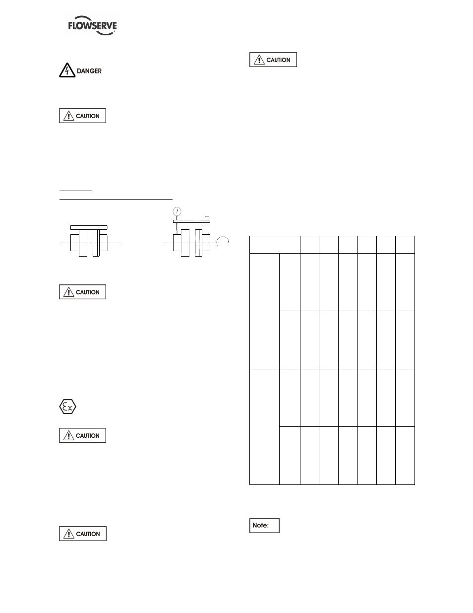
Alignment
Parallelism and concentricity check
with a rule
with a comparator
If the motor stool is fitted with a
screw adjustment, take 3 or 4 measurements at
different places.
Admissible margin for a motor with roller bearings
= 0.15 mm parallel checking
Otherwise: there are no coupling checks regarding
parallelism or concentricity. Owing to the design of
the machine the set is self-aligning.
4.5 Piping
The user must verify that the equipment is
isolated from any external sources of vibration.
Protective covers are fitted to the
pipe connections to prevent foreign bodies
entering during transportation and installation.
Ensure that these covers are removed from the
pump before connecting any pipes.
4.5.1 Discharge pipework
The dimensions of the pipes do not directly
depend on discharge diameter of the pump. First,
choose a flow speed about 3 m/s at discharge.
Never use pump as a support for
piping.
Do not mount expansion joints in
such a way that their force, due to internal
pressure, may act on the pump flange.
Maximum forces and moments allowed on the
pump flanges vary with the pump size and type.
Greater forces or moments may cause
misalignment, hot bearings, worn couplings,
vibrations and the possible failure of the pump
casing.
When designing the pipes (§ 4.5.2) take
necessary precautions in order not to exceed the
maximum allowed forces.
Forces and moments applied to the pump flanges
must never exceed the values shown in the table
below:
For pumps in steel or alloy steel:
DN
250
300
400
500
600
700
Fx
445
535
720
900
1080 1260
Fy
405
485
650
810
970
1130
Fz
500
600
800
1000 1200 1400
ΣΣΣΣ
F
785
940
1250 1560 1880 2195
Mx
220
300
480
710
1000 1320
My
270
360
580
870
1210 1550
Mz
190
260
420
610
860
1120
D
is
c
h
a
rg
e
a
b
o
v
e
t
h
e
m
o
u
n
ti
n
g
p
la
te
ΣΣΣΣ
M
390
530
860
1280 1800 2320
Fx
149
179
230
299
359
419
Fy
135
161
215
269
323
377
Fz
167
200
266
332
398
464
ΣΣΣΣ
F
261
313
417
521
625
729
Mx
73
99
159
236
332
434
My
89
121
194
289
404
528
Mz
63
86
138
205
288
376
D
is
c
h
a
rg
e
b
e
lo
w
t
h
e
m
o
u
n
ti
n
g
p
la
te
ΣΣΣΣ
M
131
178
286
426
598
782
F = Force in daN
M = Moment in m.daN
FR = Resultant force
Mr = Moment resultant
For cast iron pumps: these values are to
be divided by 2.