3 general arrangement drawing – Flowserve VF User Manual
Page 30
VF USER INSTRUCTIONS ENGLISH 71561233 - 11/09
Page 30 de 32
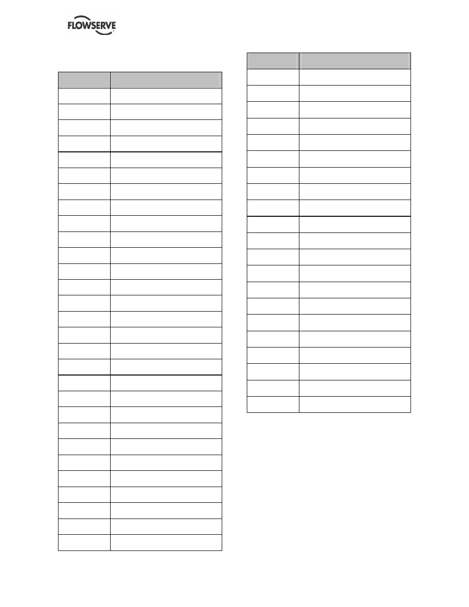
8.2 Sectional drawings part list
ITEMS
DESIGNATION
1170
Pump bowl
1310
Bellmouth
1340
Adaptor
1371
Discharge elbow
1500
Wear ring
2110
Pump shaft
2130
Top shaft
2261
Mixed flow impeller, shroudred
2450
Shaft sleeve
2461
Spacer sleeve for bearing
2472
Inner race centring sleeve with collar
2540
Thrower
2915
Shaft adjusting nut
3011
Radial ball bearing
3160
Motor stool
3244
Bearing carrier for anti-friction bearing
3250
Bearing spider
3261
Bearing cover, drive side
3400
Bearing bush
3712
Bearing nut
3853
Grease nipple
3863
Grease regulator
4110
Stuffing box housing
4130
Gland packing
4131
Follower
4134
Lantern ring
4610
Round section joint ring
6531
Suction strainer
6541
Lockwasher
ITEMS
DESIGNATION
6700
Key
7120
Muff coupling, split
7415
Coupling ring, split
9302
Shell bearing
9311
Grease nipple cap
9320
Stopping device
9402
Gland flange
9453
Evacuation pipe of stuffing box leakage
9620
Various pipe
9621
Screwed plug
9623
Union T
9626
Union joint
9638
Purger
9690
Special shackle pin
9923
Hexagon nut
9929
Self-braked nut
9930
Slotted round nut for book-spanner
9940
Special ring
9941
Plain washer
9944
Curved spring washer
9951
Stud
8.3 General arrangement drawing
The typical general arrangement drawing and any
specific drawings required by the contract will be sent
to the Purchaser separately unless the contract
specifically calls for these to be included into the
User Instructions. If required, copies of other
drawings sent separately to the Purchaser should
be obtained from the Purchaser and retained with
these User Instructions.