Flowserve FRBHJC User Manual
Page 11
FRBHJC USER INSTRUCTIONS ENGLISH 71569179 11-04
Page 11 of 36
®
2.5 Recycling and end of product life
At the end of the service life of the product or its parts,
the relevant materials and parts should be recycled or
disposed of using an environmentally acceptable
method and in accordance with local regulations. If the
product contains substances that are harmful to the
environment, these should be removed and disposed of
in accordance with current local regulations. This also
includes the liquids and/or gases that may be used in
the "seal system" or other utilities.
Make sure that hazardous substances are
disposed of safely and that the correct personal
protective equipment is used. The safety specifications
must be in accordance with the current local
regulations at all times.
3 PUMP DESCRIPTION
3.1 Configurations
Flowserve "FRBH" pumps are single stage, end
suction centrifugal pumps specifically designed for the
pulp and paper industry and consequently are ideally
suited to many process fluids. A volute type casing
with integrally cast feet and top centerline discharge
nozzle is standard. Th e semi-open impeller with rear
pump-out vanes is capable of passing pulpy material
and solids of a limited size. A rigid steel sump cover
plate supports the pump and drive system. The three
point thrust bearing housing support permits precision
bearing alignment and impeller clearance setting.
The pump liquid end is fitted with a non-flush restriction
bushing that also acts as a bearing for start -up
conditions.
All pumps are carefully inspected and prepared for
shipment. All exterior machined surfaces are coated
with a rust preventative compound and openings are
provided with covers or plugs. The axial impeller
running clearance is preset at the factory but should be
checked prior to final alignment in case of tampering.
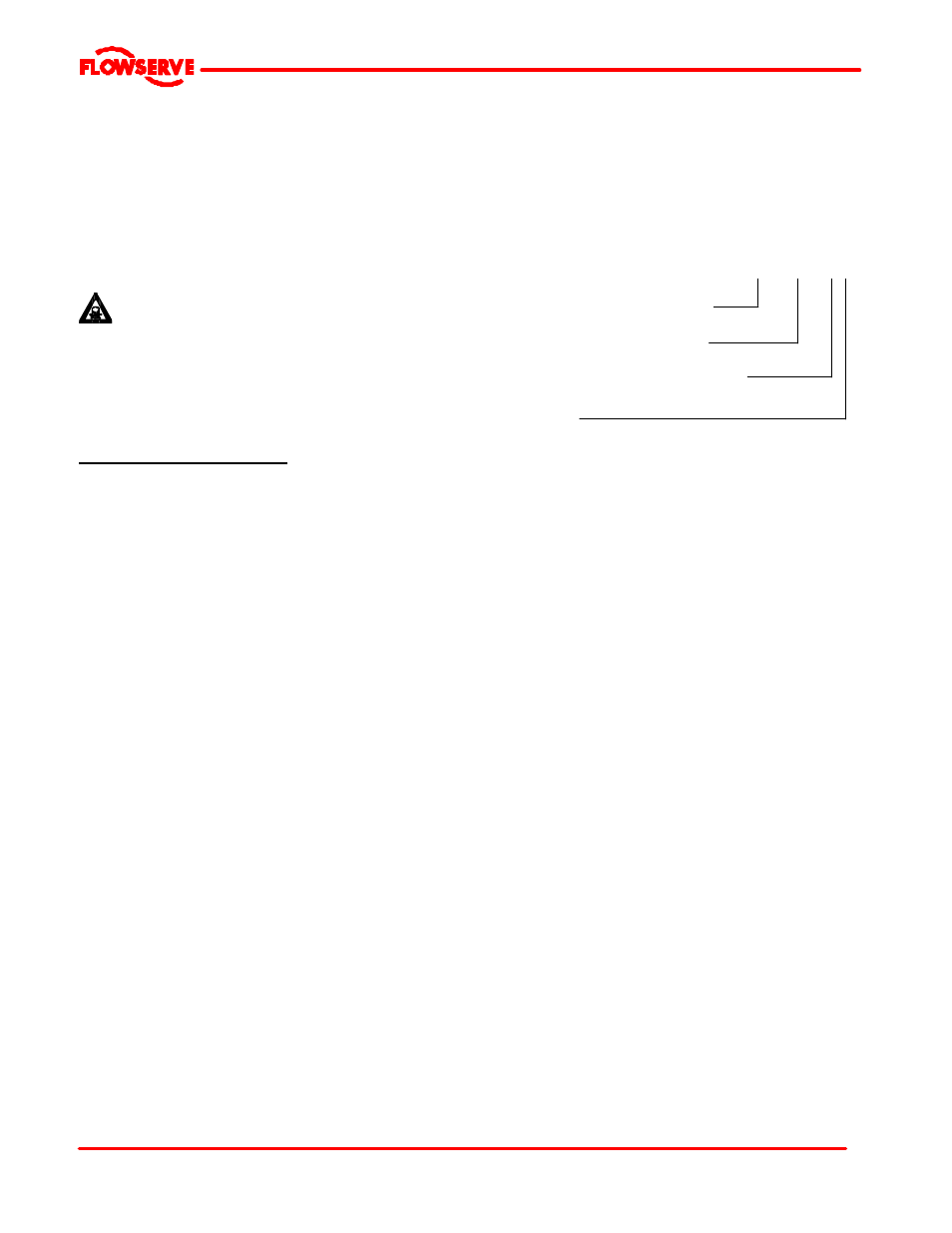
3.2 Name nomenclature
The pump size will be engraved on the nameplate. The
following example explains how the pump name
identifies the construction features and options.
8FRBH-182
Nominal discharge branch size.
Configuration – see below.
Nominal maximum impeller diameter.
Frame size
JC
is added for vertical cantilever
3.3 Design of major parts
3.3.1 Pump casing
The pump casing is a volute type casing with integrally
cast feet (for horizontal configuration) and centerline
discharge nozzle. It is a one piece pressure retaining
casting with gasket connections to the stuffing box
head and the suction and discharge flanges.
3.3.2 Impeller
The impeller is semi-open design, keyed to the shaft
and secured with a contoured impeller nut.
3.3.3 Shaft
The large diameter stiff shaft, mounted on bearings,
has a keyed drive end.
3.3.4 Pump bearings and lubrication
Ball bearings are fitted as standard and grease
lubricated. The inboard bearing located just above the
top plate is pregreased and is sealed for life. Greasing
if necessary will only be required for the lip seal that
seals the bearing housing. The outboard bearing cover
has a grease fitting accessible through the motorstand.
3.3.5 Stuffing box housing
The stuffing box or lower housing has a spigot (rabbet)
fit between the pump casing and bearing housing for
optimum concentricity. The design enables a number
of sealing options to be fitted for horizontal
configuration.