Flowserve FRBHJC User Manual
Page 34
FRBHJC USER INSTRUCTIONS ENGLISH 71569179 11-04
Page 34 of 42
®
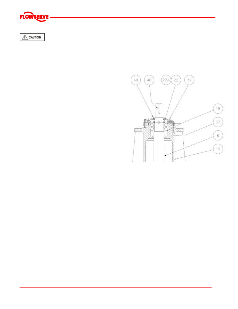
6.11 Setting Impeller Clearance
Never attempt to change the clearance when the
pump is running.
If the coupling has limited axial adjustment capability, the
pump and driver must be uncoupled prior to adjusting the
clearance in order to permit free movement.
a) Loosen the thrust bearing housing jam nuts and back
off the three jacking screws at least 1.5 mm (0.06 in.).
b) Move the rotor towards the wear plate [181] by
tightening the three hold-down capscrews evenly and
uniformly until the impeller [2] just touches the wear
plate [181]. This can be best established by rotating
the shaft and stopping the forward motion at the first
sign of rubbing. If the shaft cannot be rotated, back
off the bearing housing with the jacking screws until a
just detectable rub is obtained.
c) Set a dial indicator on the end of the shaft or the
flange of the bearing housing [33]. Set dial to “0”.
d) Determine the required impeller axial running
clearance from Engineering Tables of Section 3.4
e) Loosen the thrust bearing housing hold down
capscrews slightly and tighten the jack screws to
achieve the clearance reading on the dial indicator.
f) Alternately and gradually tighten the hold down
capscrews and jack screws while maintaining the
reading on the dial indicator. The gap between the
housing and the bearing frame should be even within
0.08mm (0.003 in.). .
g) While preventing the jack screws from rotating, tighten
h) the jam nuts to lock them in position.
i)
Manually rotate the shaft to ensure that there is no
rubbing or binding.
j)
On belt driven units, adjust the pump or driver sheave
to maintain belt alignment. (Section 4.5).
k) Check the alignment on direct driven units (refer to
Section 4.5) and reassemble the coupling
components.
l)
Replace any safety guards that may have been
removed.