2 pump lubricants, 3 direction of rotation, 4 guarding – Flowserve FRBHJC User Manual
Page 25: 5 priming and auxiliary supplies, 6 starting the pump
FRBHJC USER INSTRUCTIONS ENGLISH 71569179 11-04
Page 25 of 42
®
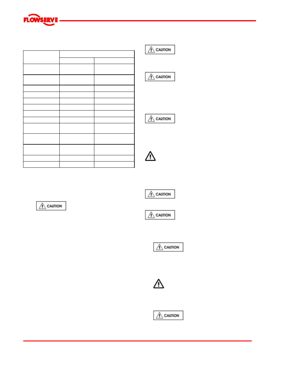
5.2 Pump lubricants
5.2.1 Recommended grease lubricants
Grease nipples
Grease
NLGI 2 *
NLGI 3 **
Temp. range ºC
(ºF)
-20 to +100
(-4 to +212)
-20 to +100
(-4 to +212)
Designation
according to DIN
K2K-20
K2K 30
BP
Energrease LS2
Energrease LS3
DEA
Glissando 20
Glissando 30
Elf
Elfmulti 2
Elfmulti 3
Ess o
Beacon 2
Beacon 3
Mobil
Mobilux 2
Mobilux 3
Q8
Rembrandt 2
Rembrandt 3
Shell
Alvania Fett G2
Alvania Fett R2
Alvania R3
Texaco
Multilak 20
Multilak EP2
Multilak 30
Multilak EP3
Wintershall
(BASF Group)
Wiolub LFK 2
-
SKF
LGMT 2
LGMT 3
Silkolene
G55/T
G56/T
* NLGI 2 is an alternative grease and is not to be mixed with other
grades
** Factory packed bearings for the temperature range with grease
nipples
5.2.2 Recommended fill quantities
Refer to section 3.4.2, Pump and impeller data.
5.2.3
Lubrication schedule
5.2.3.1 Grease lubricated bearings
When grease nipples are fitted, one charge between
grease changes is advisable for most operating
conditions, ie 2 000 hours interval.
Normal intervals between grease changes are 4 000
hours or at least every 6 months.
The characteristics of the installation and severity of
service will determine the frequency of lubrication.
Lubricant and bearing temperature analysis can be useful
in optimising lubricant change intervals.
The bearing temperature may be allowed to rise to
55 ºC (131 ºF) above ambient but should not exceed 95
°
C (204
°
F). For most operating conditions a quality
grease having a lithium soap base and NLGI consistency
of No 2 or No 3 is recommended. The drop point should
exceed 175 ºC (350 ºF).
Never mix greases containing different
bases, thickeners or additives.
5.3 Direction of rotation
Ensure the pump is given the same
rotation as the pump direction arrow cast on the pump
casing.
To avoid dry running the pump must either be filled with
liquid or have the flexible coupling disconnected before
driver is switched on.
If maintenance work has been carried
out to the site's electricity supply, the direction of
rotation should be re-checked as above in case the
supply phasing has been altered.
5.4 Guarding
Guarding is supplied fitted to the pump set. If this
has been removed or disturbed ensure that all the
protective guards around the pump coupling and
exposed parts of the shaft are securely fixed.
5.5 Priming and auxiliary supplies
Ensure all electrical, hydraulic,
pneumatic, sealant and lubrication systems (as
applicable) are connected and operational.
Ensure the inlet pipe and pump casing
are completely full of liquid before starting continuous
duty operation.
5.6 Starting the pump
a)
Ensure flushing and/or cooling/
heating liquid supplies are turned ON before
starting the pump.
b) CLOSE the outlet valve.
c) OPEN all inlet valves.
d) Prime the pump.
e)
Ensure all vent connections are closed before
starting.
f) Start motor and check outlet pressure.
g) If the pressure is satisfactory, slowly OPEN outlet
control valve.
h)
Do not run the pump with the outlet
valve closed for a period longer than 30 seconds.