Flowserve FRBHJC User Manual
Page 32
FRBHJC USER INSTRUCTIONS ENGLISH 71569179 11-04
Page 32 of 42
®
b) Lightly lubricate the shaft [6] at the bearing
position.
c) Use an induction heater or oil bath to first heat up
the line bearing [16] to 100
°
C (210
0
F). Press the
bearing on the shaft with the aid of a sleeve
designed to push the inner race only.
Note that the inner race must seat on the shaft sleeve
shoulder.
d) After the bearing has cooled, protect the bearing by
wrapping with a clean lint free cloth.
e) Slide the retaining ring [706] over the shaft and
place in groove.
f) The bearings are sealed for life and do not need
greasing.
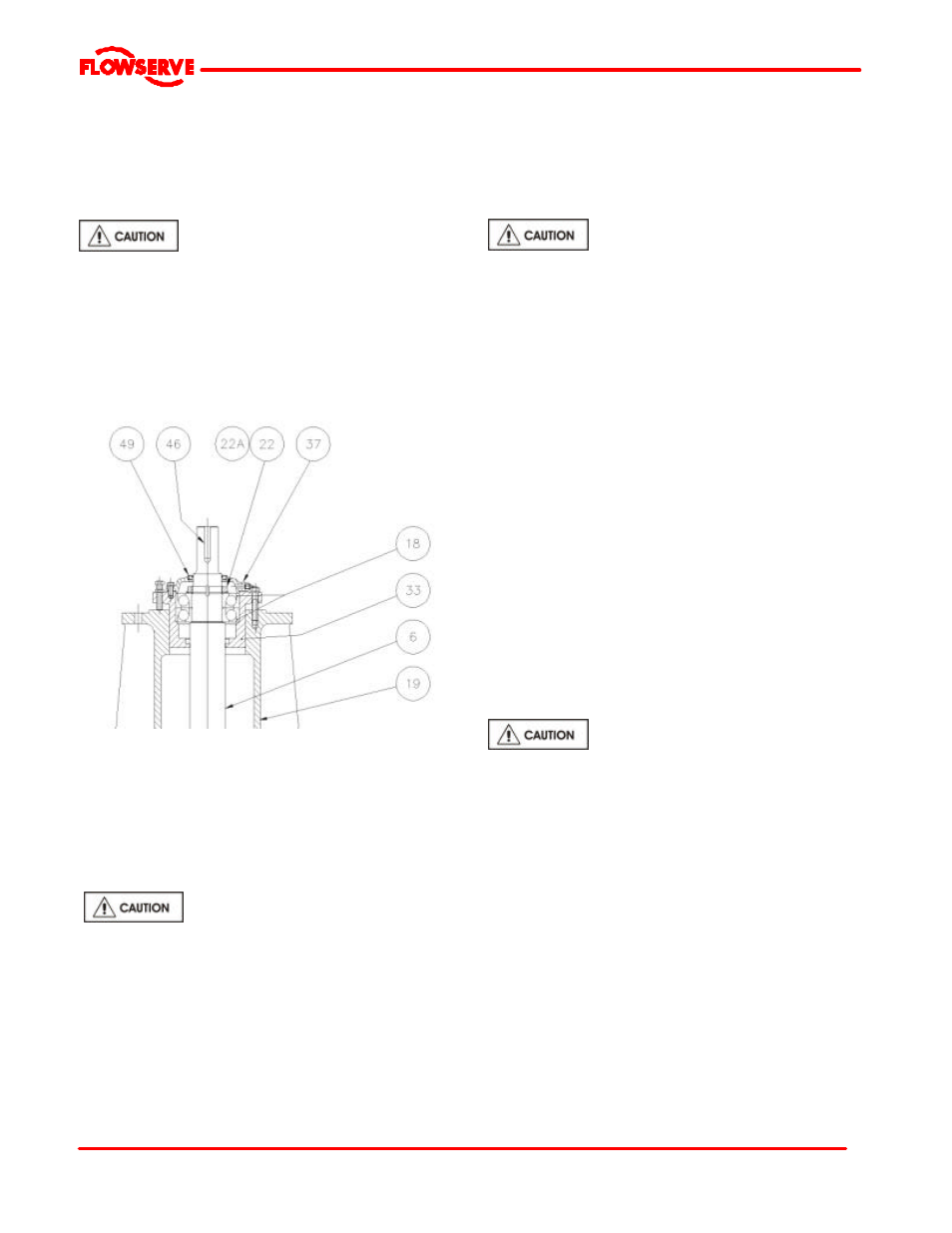
6.10.3 Thrust Bearings
a) Slide the thrust bearing housing [33] onto the shaft
[6] between the line bearing [16] and thrust bearing
[18] Location.
b) Lightly lubricate the shaft [6] at the bearing
position.
c) Use and induction heater or not oil bath to heat the
bearings to 100
°
C (210
0
F). Install the thrust
bearings [18] as noted below.
Note that the angular contact bearings are mounted
back-to-back, commonly called the “O” arrangement.
The inner race must seat on the shaft shoulder.
d) Slide the bearing lockwasher [22A] on the shaft
and fit the bearing locknut [22]. Tighten the locknut
snugly and allow to cool. Check the tightness and
bend one lockwasher tab over to lock the nut.
e) Pack the thrust bearings [18] with grease.
f) Slide the thrust bearing housing [33] over the
bearings.
g) Install the grease fitting into the thrust bearing
cover [37].
h) Carefully install the lip seal [49] or labyrinth seal
into the thrust bearing cover [37] by pressing
squarely into the bore.
i)
Slide the thrust bearing cover over the shaft.
Care must be taken to ensure that the lip
seal is not damaged on the shaft keyway.
j) Secure to the thrust bearing housing using the
capscrews and lockwashers, tighten in accordance with
Table in section 6.6.
6.10.4 Bearing Frame
a) Place the top plate [23] in a vertical position and
block in place with angle plates.
b) Bolt the bearing frame [19] to the top plate [23].
Use Loctite A on the capscrew threads - tighten in
accordance to Table 6.6.
c) Slide the shaft assembly through Bearing Cartridge
[19] from the drive end and align to the adjusting
bolt holes.
d) Assemble adjusting bolts and hardware.
6.10.5 Lower Column
6.10.5.1 Integral line bearing cover
In some designs the line bearing cover is integral with
the column support pipe [101]
a) Place the support pipe [101] in a horizontal position
on a V-block arrangement and install lip seal [47]
with the primary sealing lip away from the bearings.
b) Lubricate the shaft/sleeve for the line bearing seal.
c) Lift the support pipe and carefully install over the
shaft and to the top plate/bearing frame assembly.
The sealing lip could be damaged during the assembly
if adequate precaution not taken.
d) Fasten the support pipe to the top plate/bearing
frame assembly. Use Loctite “A”, thread locking
compound on all capscrew threads. Tighten in
accordance with Table 6.6.
6.10.5.2 Loose line bearing cover
a) Install the lipseal [47] or labyrinth seal in the line
bearing cover [37]. Place the lipseal with the
primary sealing lip away from the bearings. For
labyrinth seals the shoulder is outside and away
from the bearings.
b) Lubricate the shaft/sleeve for the line bearing seal.
c) Install the line bearing cover to the bearing frame
[19] and fasten in place with appropriate fasteners.
d) Lift the support pipe and carefully install over the
shaft and to the line bearing cover.