Flowserve FRBHJC User Manual
Page 33
FRBHJC USER INSTRUCTIONS ENGLISH 71569179 11-04
Page 33 of 42
®
6.10.6 Grease Fitting, frame 3
a) Install the appropriate grease fitting to the bearing
frame at the line bearing.
b) Charge grease fitting with grease
6.10.7 Bearing Frame Vent
a) Install street elbow in bearing frame and orientate
elbow to towards drive end of shaft.
b) Install Inpro vent valve
6.10.8 Stuffing Box area
a) Clean the shaft where the shaft sleeve [14] will be
located.
b) Prepare shaft and sleeve with Loctite Primer
c) Apply Loctite A to shaft.
d) Install the shaft sleeve [14] onto the shaft [6] while
turning the sleeve to spread the Loctite sealant
over the inside surface of the sleeve.
e) Assemble the throat bushing [63] into the lower
housing [33A].
f) Apply Loctite A to periphery of elastomeric bushing
[39] at one end and slide into housing [33A] using a
twisting motion. Wipe away excess compound. If
provided, install studs and fit clamp plate to hold
bushing in place.
g) Slide the lower housing [33a] over shaft and into
spigot to support pipe [101]. Clamp into position
using ‘C’ clamps.
h) Using adjusting bolts on thrust bearing housing [33]
adjust shaft forward so that the end of the sleeve
protrudes slightly beyond the face of the lower
housing [11].
i)
Install impeller key [32], smear anti-seize
compound onto the shaft at the impeller location.
j)
Slide impeller [2] onto the shaft [6].
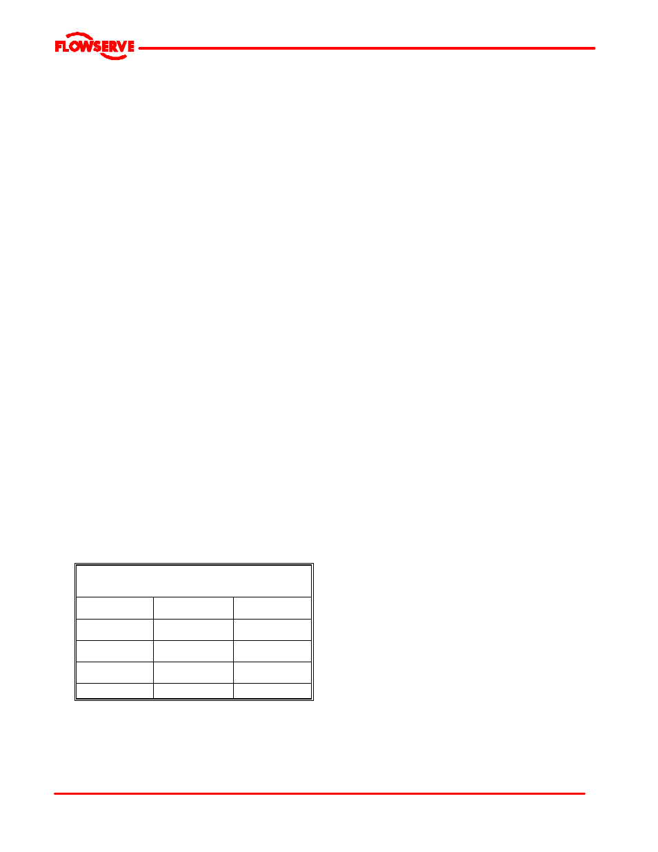
k) Apply Loctite A to shaft threads and install the
impeller nut [24]. Torque impeller nut as indicated
in table below:
6.10.9 Casing
a) Place the casing on the suction nozzle.
b) Screw the wear plate studs into the wear plate.
Apply Loctite A to threads.
c) Place sealing washers over the studs. A small
amount of grease may be used to hold them into
position during assembly of wear plate.
d) Lower the wear plate [181] studs first into the
casing [1], align the studs with the casing holes.
e) Fasten the wear plate [181] to the casing using the
washers, nuts and Loctite A on nuts. Tighten in
accordance with Table 6.6.
f) Remove ‘C’ clamp from housing. Smear the casing
gasket [73] with a grease and position on lower
cover [33A].
g) Release thrust bearing housing hold down bolts.
h) Lift the casing [1] and slide over the impeller and
onto the lower housing [33].
i)
Align discharge of casing [1] with slot in top plate
[23]
j)
Bolt casing [1] into position using Loctite 242 on
threads. Tighten bolts in accordance with Table
6.6.
TABLE 6.10.8
MINIMUM IMPELLER NUT
TIGHTENING TORQUE
FRAME
Ft. lbs.
Nm.
1
100
140
2
300
400
3
300
400