Checking or setting internal regulator pressure, Figure 11: internal regulator, Figure 12: driver module – Flowserve 1400 Valtek Logix User Manual
Page 10
46-10
Flowserve Corporation, Valtek Control Products, Tel. USA 801 489 8611
4. Obtain a No. 10-32 x swivel elbow (Pneumadyne part
No. SFL-10 or equivalent).
5. Remove No. 10-32 x .016 orifice (Figure 4) from the
driver module, and screw in No. 10-32 x swivel elbow.
6. Direct the swivel elbow so the minimum pressure
test port is accessible.
7. Screw a No. 10-32 x
1
/
16
-inch barb fitting into the test
port, and screw the No. 10-32 x .016 orifice into the
end of the elbow as shown.
8. Connect the tubing from the internal regulator output
port to the orifice.
9. Using some
1
/
16
-inch flexible tubing, connect a 0 to
30 gauge to the minimum pressure set port.
10. Once the gauge is connected, reapply the positioner
air supply. The minimum pressure should now be
registering on the gauge and must be 3.8 to 4.2 psi.
If the minimum pressure is not correct, use a
9
/
64
-inch Allen wrench to turn the minimum pressure
set screw located at the bottom of the driver module
(Figure 3) until the pressure is in the range indicated.
Cycle the positioner air supply several times and
recheck the minimum pressure and readjust, if
necessary, to ensure that the pressure has settled
within the range specified.
11. When the pressure is set, remove the air supply.
12. Remove the No. 10-32 x
1
/
16
-inch barb and orifice from
the swivel elbow and then remove the swivel elbow.
13. Replace the orifice as shown in Figure 4 and
reconnect the
1
/
16
-inch tubing from the internal regu-
lator output port to the orifice. Reconnect the posi-
tioner air supply and power. The positioner should
now be ready to calibrate.
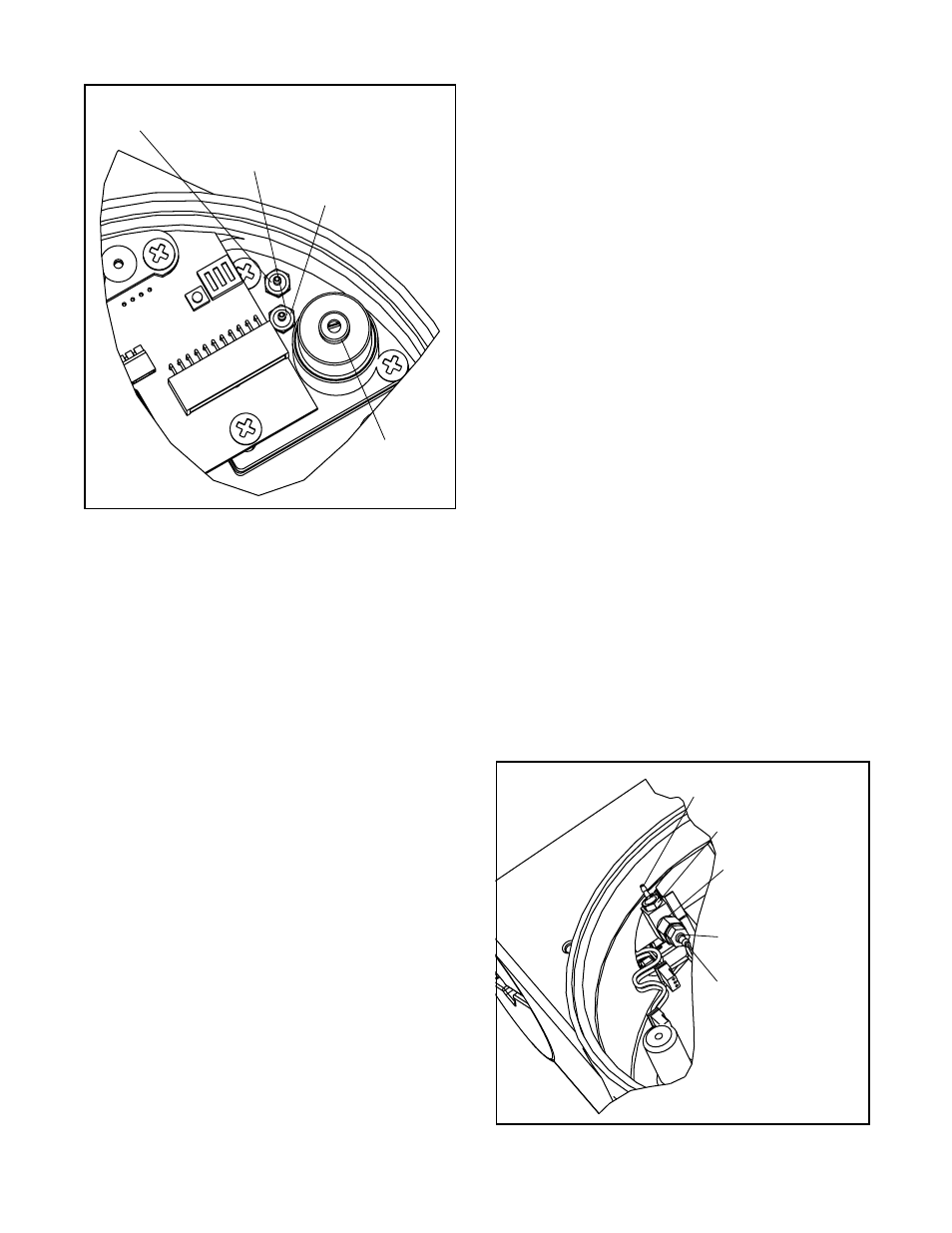
Checking or Setting Internal Regulator
Pressure
1. Disconnect the air supply from the positioner.
2. Remove the main cover. The regulator pressure set
port is factory plugged with a No. 10-32 hex plug
(Figure 11). Replace hex plug with a No. 10-32 x
1
/
16
-inch barb fitting.
3. Attach a 0 to 30 psi pressure gauge (with some
1
/
16
-inch flexible tubing) to the barb fitting shown in
Figure 11.
4. Reconnect the air supply to the positioner and read
the internal regulator pressure on the 0 to 30 gauge
(the internal regulator should be set to 22.0 psi).
Adjust the regulator pressure by turning the set
screw with a small flat screwdriver.
5. Once the regulator pressure is set, remove the air
supply to the positioner, and replace the No. 10-32 x
1
/
16
-inch barb fitting with the No. 10-32 hex plug.
Checking or Setting the Driver Module
Minimum Pressure
Once the internal regulator pressure is set to 22.0 psi, the
driver module minimum pressure can be checked. To do
this, refer to Figure 12, and proceed as follows:
1. Make sure valve is bypassed or in a safe condition.
2. Disconnect power from the positioner.
3. Remove the main cover and remove the
1
/
16
-inch
flexible tubing from the orifice.
Figure 11: Internal Regulator
This port is Internal Regulator Output. This
should be tubed to orifice on Driver Module.
Check pressure through
No. 10-32 x
1
/
16
Barb fitting
Regulator Pressure
Test Port
Internal
Regulator
Set Screw
Figure 12: Driver Module
Minimum Pressure
Test Port
No.10-32 x
1
/
16
-inch
barb
No.10-32 x Swivel
ELL Pneumadyne
Part No. SFL-10
No.10-32 x .016
Orifice
Pressure from
Internal Regulator
to be tubed to this
orifice