Figure 2: field termination driver module assembly, Driver module assembly replacement, Figure 3: driver module assembly – Flowserve 1400 Valtek Logix User Manual
Page 5
46-5
Flowserve Corporation, Valtek Control Products, Tel. USA 801 489 8611
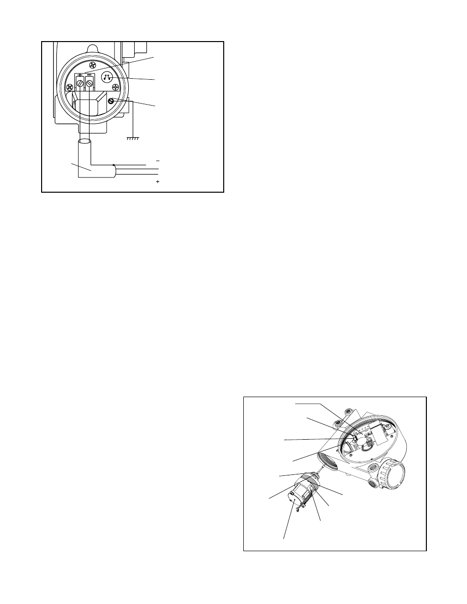
Field Terminations
FB Connection
Terminals
Housing EARTH
Terminal
Shielded
Cable
Figure 2: Field Termination
Driver Module Assembly
The driver module assembly moves the spool valve by
means of differential pressures on its diaphragm. Air is
routed to the module from the interface plate through a
hose that connects to the assembly through a hose barb
with an integral orifice. Wires from the module connect
the hall effect sensor and the pressure modulator coil to
the collector board.
Driver Module Assembly Replacement
To replace the driver module assembly, refer to Figures
3 - 5, 7 and 19 then proceed as outlined below. The
following tools are required:
1
/
4
-inch open-end wrench
1
/
2
-inch hex wrench
Phillips screwdriver
Driver Module removal tool
1. Make sure valve is bypassed or in a safe condition.
2. Disconnect the power and air supply to the unit.
3. Remove the driver module cover, using a
1
/
2
-inch hex
wrench (Figure 4). Do not force the cover. If undue
resistance is encountered, use the slots to loosen
cover.
4. Remove the spool valve cover by removing the
screw and sliding the cover assembly backwards
until the tab is clear of the slot. It is not necessary
to remove the sheet metal cap from this assembly
(Figure 7).
5. Being careful not to lose the nylon washers, remove
the two phillips-head screws that attach the driver
module to the main housing (Figure 5).
6. Remove the spool valve block by removing the two
phillips-head screws and carefully sliding the block
off the spool (Figure 5).
Ground
Fieldbus
connection
CAUTION: The spool (extending from the driver
assembly) is easily damaged. Use extreme cau-
tion when handling driver assembly.
7. Remove the tubing from the orifice in the driver
module assembly. Using a
1
/
4
-inch open-end wrench,
remove the orifice from the driver module (Figure 4).
8. Remove the two wiring connections that link the
driver module assembly to the collector board.
(Figure 4).
9. Feed the wires back through the housing so they
extend backward toward the driver module opening.
This will allow the driver module to thread out without
tangling the wires.
10. Grasp the driver module cap with the driver module
removal tool and rotate the entire driver module
counter clockwise to remove. After it is threaded out,
carefully retract the driver module from the housing
to avoid damaging the spool.
11. Take the new driver module and verify that the O-ring
and boot are in place. Lay the wires back along the
modulators as shown in Figure 3 and hold in place.
12. Gently direct the driver module into the housing bore,
making sure the spool does not hit the housing. Turn
driver module clockwise to thread it into the housing.
Continue rotating the module until it bottoms out.
13. Once the threads are fully engaged, rotate the driver
module counter clockwise until the flat on the driver
module and the flat on the housing are aligned. This
will align the screw holes for the next step (Figure 3).
14. Verify that nylon gaskets are in the counter bores in
the driver module retaining screw holes as shown in
Figure 5.
15. Insert two driver-to-housing screws into the driver
housing through the counter-bored holes in the
positioner main housing. Tighten evenly with a phillips
screwdriver.
Figure 3: Driver Module Assembly
Collector Board
Pressure Modulator
Connection
Hall Sensor
Connection
Flat in Housing
Protective
Boot
O-ring
Minimum Pressure Set Screw (factory calibrated)
Driver Module Assembly
Install orifice after driver
module is in housing
Orient this flat parallel
to flat in housing