Flowserve 1400 Valtek Logix User Manual
Page 7
46-7
Flowserve Corporation, Valtek Control Products, Tel. USA 801 489 8611
6. Insert new coalescing filter into the bore on interface
plate.
7. Verify that the O-ring is in place in filter housing.
8. Set filter housing over coalescing filter and secure
with four No. 6-32 screws.
9. Replace collector board and reconnect wiring.
Main PCB Assembly
The main PCB assembly contains the circuit boards and
processor that perform the control functions of the
positioner. The boards are conformal-coated with a
protective silicon coating. This module can be easily
replaced if positioner upgrades are desired. None of the
components are user-serviceable. This module is to be
replaced as an entire unit.
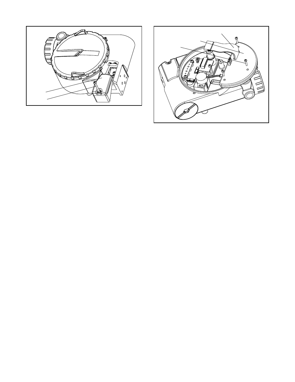
Replacing Main PCB Assembly
(Figure 8)
1. Make sure valve is bypassed or in a safe condition.
2. Disconnect the power and air supply to the unit.
3. Remove the main cover and disconnect the ribbon
cable from the collector board.
CAUTION: To avoid damaging any components,
exercise caution by gently raising the locking tab
to release the ribbon cable.
4. Remove the PCB assembly by removing the three
No. 6-32 screws and lifting out of housing.
5. Place the new PCB assembly on bosses inside the
positioner housing.
6. Insert three No. 6-32 screws through the boards, with
the nylon washers on the bottom into the threaded
bosses and tighten evenly, using a phillips screw-
driver. Do not overtighten.
7. Reconnect the ribbon cable to the collector board.
Regulator
The regulator reduces the pressure of the incoming
supply air to a level that the driver module can use.
Replacing Regulator
1. Make sure valve is bypassed or in a safe condition.
2. Disconnect the power and air supply to the unit.
3. Remove the main cover and unscrew the regulator
from the interface plate, exercising caution not to
damage the collector board (Figure 19).
4. Verify that the O-rings are in place on the base of the
new regulator
5. Replace the regulator by threading into the port on
the interface plate.
6. Check regulating pressure to ensure that it is set at
22 psi.
Internal Coalescing Filter
The internal coalescing filter ensures that supply air is
clean and dry before it gets to the regulator. Because the
air has already been filtered before this point, the element
should not require extended maintenance.
Replacing Input Filter Element
(Figure 19)
1. Make sure valve is bypassed or in a safe condition.
2. Disconnect the power and air supply to the unit.
3. Remove the main cover and remove collector board
by disconnecting the wiring and removing three
screws that attach it to the housing. Each cable has
its own unique connector to prevent improper
connections.
4. Remove the four No. 6-32 hex screws from the filter
housing and remove filter housing.
5. Remove the old coalescing filter from the bore in the
interface plate.
Figure 7: Spool Valve Cover Assembly
Spool Valve
Cover
Screw
Figure 8: Main PCB Assembly
Ribbon Cable
Main PCB Assembly
Screws (3)