Figure 15: optional rotary mounting – Flowserve 1400 Valtek Logix User Manual
Page 14
46-14
Flowserve Corporation, Valtek Control Products, Tel. USA 801 489 8611
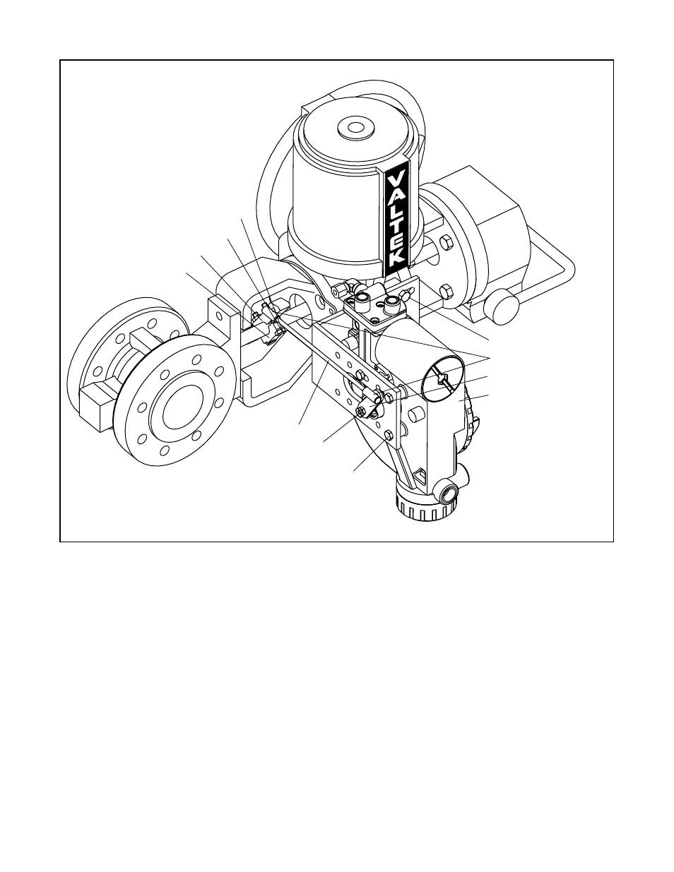
Bolts (2)
Locknuts (2)
Tripper
Tripper Clamp
*Tie Rod
Bracket Bolts
5
/
16
-18 (2)
Ball Joint Ends
Follower Arm
Rotate Positioner 90
°
* Tie Rod must be cut to desired length
Nut No. 10-32
Lock Washer
Mounting Bolts
1
/
4
-20 (4)
Figure 15: Optional Rotary Mounting
NOTE: Variable names in Figure 16 are for internal posi-
tioner use and are not directly accessible via fieldbus.
The Logix 1400 digital positioner receives power from the
two-wire, fieldbus input signal. A digital signal, sent via
fieldbus, is used as the command source.
Zero percent is always defined as the valve closed
position and 100 percent is always defined as the valve
open position.
Next, the command value is passed through a charac-
terization/limits algorithm. The positioner no longer
uses CAMs or other mechanical means to character-
ize the output of the positioner. This function is done
in software, which allows for in-the-field customer
adjustment. The positioner has two basic modes:
linear and custom characterization. In linear mode, the
command signal is passed straight through to the control
algorithm in a 1:1 transfer. In addition the user-defined
features, Soft Limits, FINAL_VALUE_CUTOFF_HI,
and FINAL_VALUE_CUTOFF_LO may affect the final
command signal. The actual command being used to
position the stem is called CMD_USED. The
CMD_USED is the actual positioning command after any
characterization or user limits have been evaluated.
The Logix 1400 digital positioner uses a two-stage stem
positioning algorithm. The two stages are comprised of
an inner-loop, spool control and an outer-loop, stem
position control. Referring again to Figure 16, a stem
position sensor provides a measurement of the stem
movement. The FINAL_VALUE command is compared
against the FINAL_VALUE_POSITION. If any deviation
exists, the control algorithm sends a signal to the inner-
loop control to move the spool, up or down, depending
upon the deviation. The inner-loop then quickly adjusts
the spool position. The actuator pressures change and