Flowserve 520MD Digital Positioner User Manual
Page 5
5
®
User Instructions Logix 520MD - LGENIM0520-01 09/09
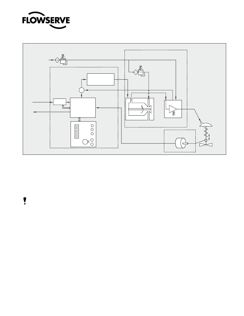
Figure 1: Logix 520MD Principle of Operation
due to the close tolerances in the positioner. Optional analog
feedback system as well as limit switch unit and a directly
attachable double acting module complete the Logix 520MD
positioner accessories.
nOTE: The air supply must conform to ISA 7.0.01or IEC 770
(a dew point at least 10 ˚C / 18 ˚F below ambient temperature,
particle size below five microns – one micron recommended
– and oil content not to exceed one part per million).
5 PRinCiPLE OF OPERATiOn
The Logix 520MD positioner is a digital positioner that incor-
porates HART protocol for communication. The positioner
consists of three main modules:
1.The microprocessor-based electronic control
module includes HART communications and direct local
user interface switches
2. The piezo valve-based electro-pneumatic converter module
3. The infinite resolution valve position sensor.
The basic positioner operation is best understood by refer-
ring to Figure 1. The complete control circuit is powered
by the two-wire, 4-20 mA command signal. The HART
module sends and receives the superimposed FSK HART
Local
User
Interface
Inner Loop
Piezo Control
Stroke
Inner Loop
Position Feedback
1 Digital Control Circuit
2 Electro-pneumatic
Converter Module
3 Valve Position
Sensor
Filter / Regulator
for Supply Air
1.5 – 6.0 bar (22 – 87 psi)
Air Supply
-
Micro-
Processor
Gain
Pressure Regulator
Piezo Valve
Pneumatic
Amplifier
Control Valve
+
4 – 20 amA
Output
(0ptional)
4 – 20 mA
+ HART
HART
digital communications over the 4-20 mA signal wires
providing two-way remote digital communications to
the microprocessor. The analog 4-20 mA command is
passed to the microprocessor, where it is compared to
the measured valve stem position. The control algo-
rithm in the processor performs control calculations
and produces an output command to the piezo valve,
which drives the pneumatic amplifier. The position of
the pilot valve in the pneumatic amplifier is measured
and relayed to the inner loop control circuit. This two-
stage control provides for more responsive and tighter
control than is possible with a single stage control
algorithm. The pneumatic amplifier controls the airflow
to the actuator. The change of pressure and volume of
the air in the actuator causes the valve to stroke. As the
valve approaches the desired position, the difference
between the commanded position and the measured
position becomes smaller and the output to the piezo
is decreased. This, in turn, causes the pilot valve to
close and the resulting flow to decrease, which slows
the actuator movement as it approaches, the new
commanded position. When the valve actuator is at the
desired position, the pneumatic amplifier output is held
at zero, which holds the valve in a constant position.