Flowserve 520MD Digital Positioner User Manual
Page 9
9
®
User Instructions Logix 520MD - LGENIM0520-01 09/09
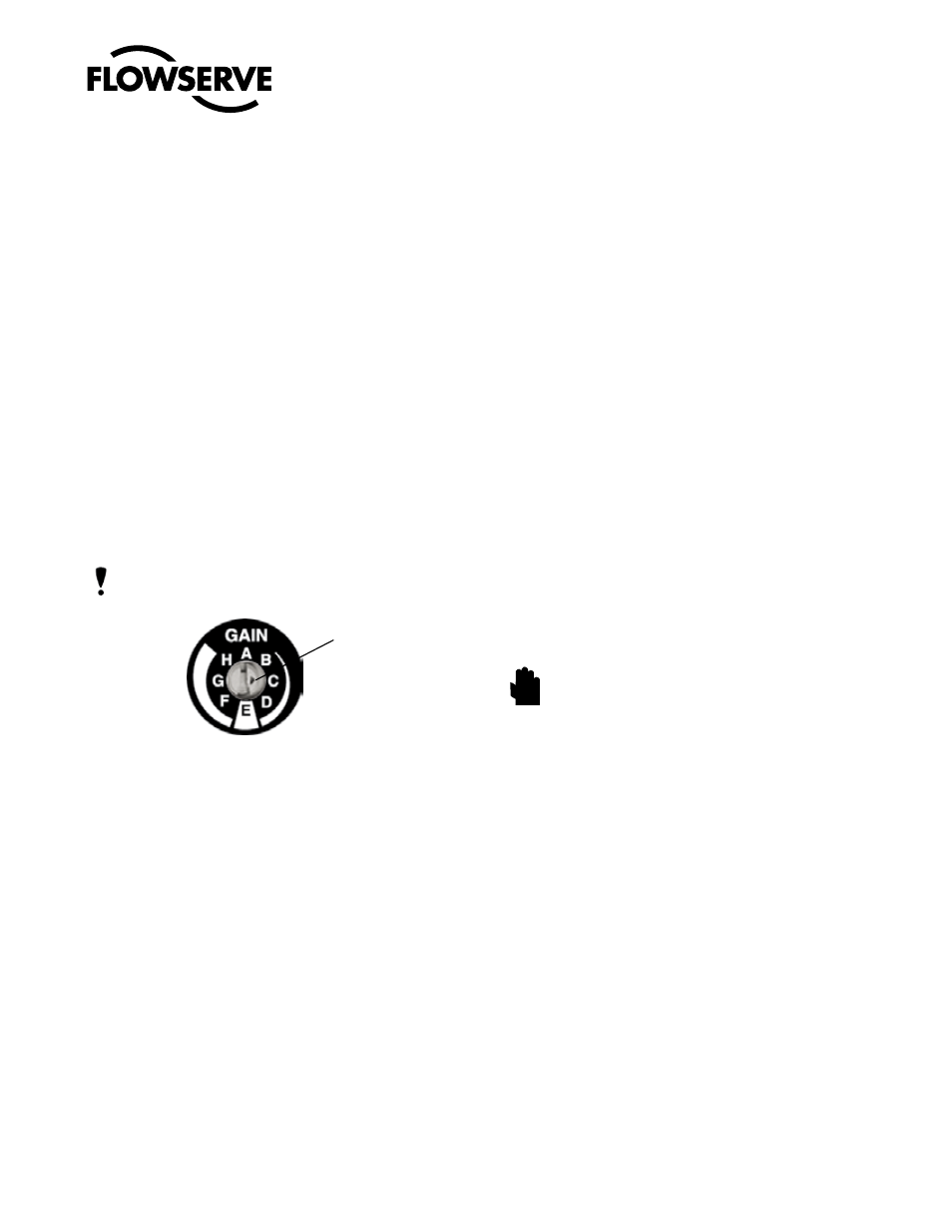
Indicator arrow
3. Pos. Characterization
Select Linear if the actuator position should be directly
proportional to the input signal.
Select Optional if another characteristic is desired, which
is set in conjunction with the next switch, labeled Optional
Pos. Char.
4. Optional Pos. Char. – If the Pos. Characterization switch
is set to optional, this switch is active with the following
options:
The =% option will characterize the actuator
response to the input signal based on a standard 30:1 equal
percent rangability curve.
If Custom is selected, the positioner will be characterized to
a custom table that must be set-up ValveSight DTM software
or a HART handheld.
5. Auto Tune – This switch controls whether the positioner will
auto tune itself every time the Quick-Cal button is pressed
On enables an auto tune feature that will automatically de-
termine the positioner gain settings every time a Quick-Cal
is performed based on the setting of the rotary Gain switch.
nOTE: there is a small black arrow indicating the selection.
The slot does not indicate the chosen gain.
If the rotary Gain selector switch is set to E with
the Auto Tune switch On, a Flowserve nominal
response tuning set will be calculated and used.
If the rotary Gain selector switch is set to D, C, B, or A with
the Auto Tune switch On, progressively lower gain settings
will be calculated and used.
If the rotary Gain selector switch is set to F, G, or H with
the Auto Tune switch On, progressively higher gain settings
will be calculated and used.
Off forces the positioner to use one of the factory preset
tuning sets determined by the rotary Gain selector switch.
Settings A through H are progressively higher gain prede-
fined tuning sets. The positioner is preset to Autotune - On
at the factory. This is the recomended setting.
The gain selector operates as a “live” switch. This means
that changes to the switch position while the positioner is in
normal operation will have immediate effect on the control
algorithm.
6. Stability Switch – This switch adjusts the position control
algorithm of the positioner for use with low friction control
valves or high friction automated valves
Placing the switch to the left optimizes the response
for low friction, high performance control valves. This
setting provides for optimum response times when used
with most low friction control valves.
Placing the switch to the right optimizes the response
for valves and actuators with high friction levels. This
setting slightly slows the response and will normally
stop limit cycling that can occur on high friction valves.
9.3 Calibration switches
9.3.1 Setup of the Cal DIP Switch for the Quick
Calibration operating mode
Select Auto if the valve/actuator assembly has an internal
stop in the 100% stroke position. In Auto mode the
positioner will fully close the valve and register the 0%
position and then open the valve to the stop to register
the 100% position when performing a self-calibration.
See detailed instructions in the next section on how to
perform an auto positioner calibration.
Select Jog if the valve/actuator assembly has no cali-
bration stop in the open position. In the Jog mode the
positioner will fully close the valve for the 0% position
and then wait for the user to set the open position using
the Jog buttons labeled with the up and down arrows.
See the detailed instructions in the next section on how
to perform a manual calibration using the Jog buttons.
WARning: During the Quick-Cal operation the valve
may stroke unexpectedly. Notify proper personnel
that the valve will stroke, and make sure the valve is
properly isolated.
9.4 Quick-Cal Operation
The Quick-Cal button is used to locally initiate a
calibration of the positioner. Pressing and holding the
Quick-Cal button for approximately three seconds will
initiate the calibration. If the Config-Switches option is
enabled, the settings of all the configuration switches
are read and the operation of the positioner adjusted
accordingly. The Gain Selector switch is also read and
action will be taken to adjust the gain according to the
settings of the calibration switches as described in the
previous section. A Quick-Cal can be aborted at any
time by briefly pressing the Quick-Cal button and the
previous settings will be retained.
If the Quick calibration switch (not to be confused
with the Quick-Cal button) is set to Auto and the valve/
actuator assembly has the necessary internal stops, the
calibration will complete automatically. While the cali-
bration is in progress you will notice a series of different
lights flashing indicating the calibration progress. When
the lights return to a sequence that starts with a green
light, the calibration is complete. (See the appendix for
an explanation of the various light sequences.)
STOP!