Limit switches & 4 - 20 ma transmitter (optional) – Flowserve APEX A9000 Accord User Manual
Page 31
31
12. Limit switches & 4 - 20 mA transmitter (Optional)
Caution!
The installation
of
electrical equipment in hazardous areas must comply with the procedures contained
in the certificates of conformity. Country specific regulations may apply.
Electrical safety is determined only by the power supply device.
12.1 General
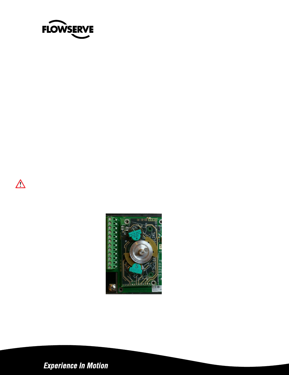
Apex A9000 can be equipped with optional plug in modules for limit switches and/or 4-20 mA feedback transmitter.
12.2 Model selection
See Apex A9000 model code
12.3 Priciple of operation
The stroke of the actuator/valve is picked up by the potentiometer inside the Apex A9000. Movement is transferred from
actuator via lever or shaft coupling. Cams/vanes mounted on the positioner shaft actuate limit switches 1 and 2. The
switching point can be adjusted on each cam/vane.
The position transmitter converts actual position into a 4-20mA output signal. This loop requires an external 12-25 VDC
power supply.
12.4 Installation
Caution! Turn off power and air supply before starting the installation.
Important!
For Apex A9000 installed in hazardous areas, maintenance and repair must only to be
made by authorized and trained staff.
-Remove cover, indicator if present and inner plastic cover.
-Check that spacers are installed on the printed circuit board.
-Carefully install feedback board into its position on the pins.
-Secure it with two (2) screws.