Flowserve APEX A9000 Accord User Manual
Page 32
32
-Install cam assembly on the shaft, if feedback card has mechanical micro switches, be careful to not
damage switch arms.
-Install plastic inner cover.
-Adjust cams/vanes to ensure proper switching.
-Secure cam/van position by locking them with two (2) screws.
-Calibrate 4-20 mA transmitter, (see next page).
-Install cover
12.5 Apex A9000 Calibration of 4-20 mA input signal and/or 4-20mA
feedback transmitter
• Press and hold button while switching on power to the Apex A9000, keep the button pressed for 6 sec. The
eeprom will now be erased, and then all three LEDs are lighted. The LEDs will start to flash yellow-red. This
starts FACTORY MODE!
To calibrate 4-20 mA input signal
• Apply 4.0 mA input signal and then push the button three (3) times until all LEDs are lighted. The LEDs will now start
flash yellow-red again.
Apply 20.0 mA input signal and then push the button three (3) times until all LEDs are lighted.
To calibrate 4-20 mA transmitter output signal
Note! If no transmitter board is installed the LEDs will start flash yellow-yellow and the unit is ready for continued
calibration. If there is a transmitter board installed the LEDs will start flash yellow-green.
The feedback transmitter output signal on pin 9 and 10 will now follow the input signal instead of the position.
Apply 4.0 mA input signal. Measure the output sig- nal and adjust the input signal up/down until the output signal is
4.0 mA. Push the button three times until all LEDs are lighted. The unit will now start to flash yellow-green again.
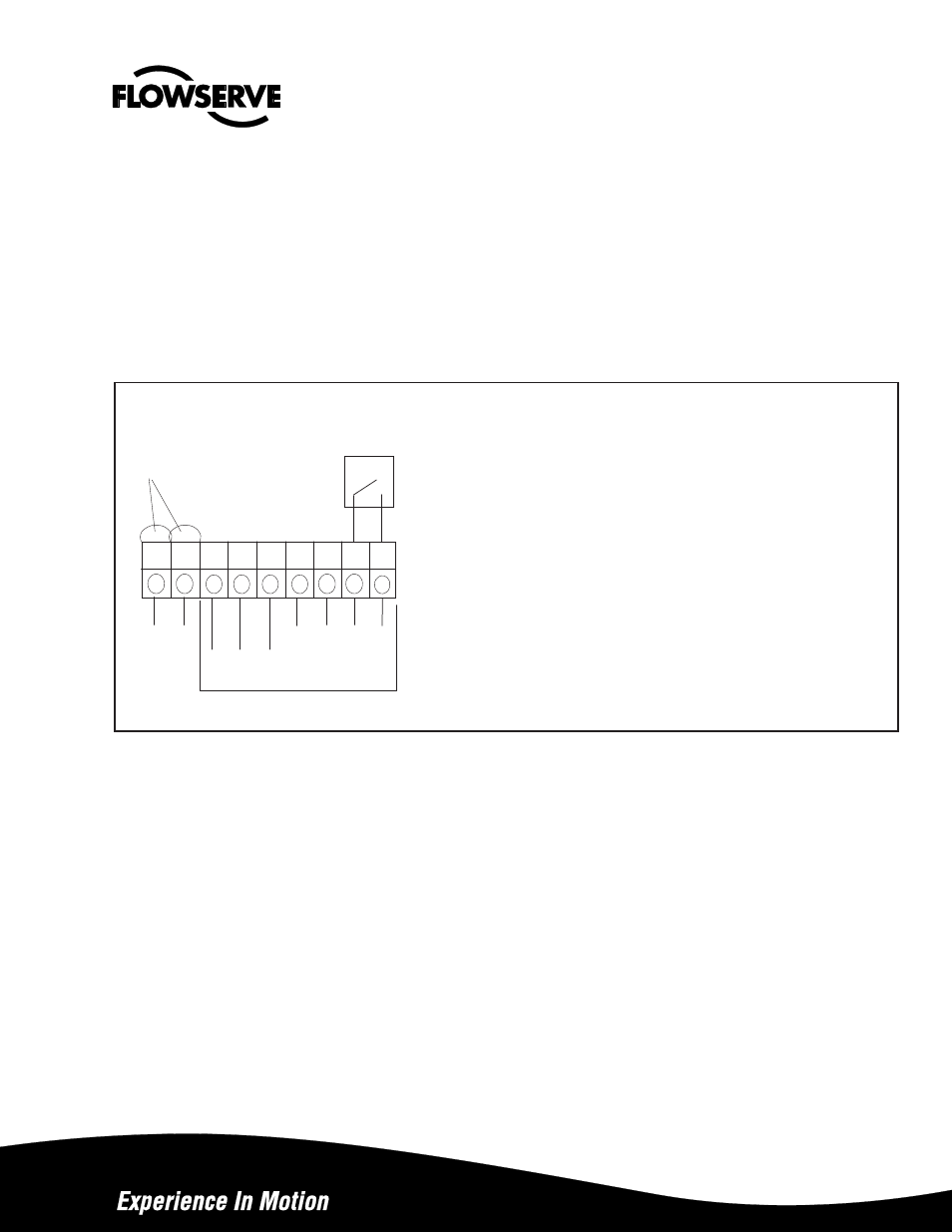
Hart
Connection
General Purpose and Intrinsically Safe
1 – Input Signal, +4-20mA, HART
2
– Input Signal, -4-20mA, HART
3
– Switch 1 output/ Remote
4
– Switch 1 output/ Remote
5
– Switch 1 output/ Remote
6
– Switch 2 output/ Remote
7
– Switch 2 output/ Remote
8
– Switch 2 output/ Remote
9 -
4-20 mA + Feedback, 13-28 V DC
10 - 4-20 mA - Feedback, 13-28 V
DC
11 - Alarm output +, 8-28 V DC
12 - Alarm output -, 8-28 V DC
Explosion Proof with LCD
1 – Input Signal, +4-20mA, HART
2
– Input Signal, -4-20mA, HART
3
– Remote
4
– Remote
5
– Remote
6
– 4-20 mA + Feedback, 13-28 V dc
7
– 4-20 mA – Feedback, 12-28 V dc
8
– Alarm output +, 8-28 V dc
9
– Alarm output -, 8-28 V dc
Explosion Proof with LED’s
1
– Input Signal, +4-20 mA, HART
2
– Input Signal, -4-20 mA, HART
3
– Remote
4
– Remote
5
– Remote
6
– 4-20 mA + Feedback, 13-28 V dc
7
– 4-20 mA – Feedback, 13-28 V dc
+
-
+
-
+
-
Remote Unit
Option