3 hardware interface, 4 network cable – Flowserve Limitorque MX DeviceNet Field Unit User Manual
Page 12
Limitorque MX DeviceNet Field Unit FCD LMENIM2328-00 – 11/05
12
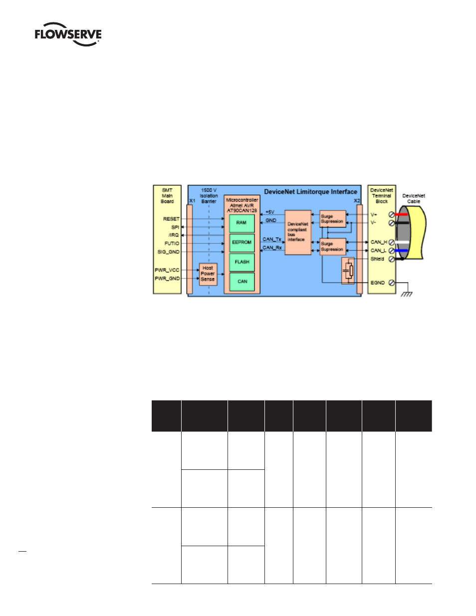
2.2.3 Hardware interface
The DeviceNet Limitorque Interface is comprised of a minimum of one PCB with two interfaces - One
for the DeviceNet Terminal Block connector and one for the SMT Main Board.
Figure 2.3 gives an overview about the hardware. The microcontroller on the DeviceNet Limitorque
Interface handles the DeviceNet protocol, stores the DeviceNet parameters in an EEPROM, and commu-
nicates with the SMT Main Board via SPI.
Figure 2.3 – DeviceNet Limitorque Interface
2.2.4 Network Cable
DeviceNet is a CAN - based protocol that uses 5 wires including a shield. Two of the conductors are
used for 24V DC power & up to 8 amps (4 amps for NEC Class 2) may be passed along the hi-way from
a suitable power source. Two conductors are used for the CAN bus signals, CAN_H and CAN_L, which
are usually smaller in diameter. Limitorque recommends Belden cable for connecting to a DeviceNet
network. The specifications for thick and thin cable (per site requirements) are as follows:
Table 2.2 – Belden Cable Specifications
Belden
Part No.
AWG
(Stranding)
dia. Inches
Nom. DCR
Insulation
material
(color code)
Nominal
O.D.
Nom
Impedance
(ohms)
Nominal
Capacitance
Test
Frequency
(MHz)
Maximum
Attenuation
dB/100ft
3082A
2 – 15 AWG
(19 x 28)
3.6 ohm/1000 ft
11.8 ohm/km
Power pair
(Black/Red)
12.2 mm
120
12.0 pF/ft
0.125
0.5
1
0.13
0.25
1.36
2 – 18 AWG
(19 x 30)
6.9 ohm/1000 ft
22.7 ohm/km
Data pair
(Blue/White)
3084A
2 – 22 AWG
(19 x 34)
17.5 ohm/1000 ft
57.4 ohm/km
Power pair
(Black/Red)
7.2 mm
120
12.0 pF/ft
0.125
0.5
1
0.29
0.50
1.70
2 – 18 AWG
(19 x 36)
28.0 ohm/1000 ft
91.9 ohm/km
Data pair
(Blue/White)