Flowserve F39 Series Pneumatic Actuator User Manual
Page 10
10
®
Series F39 Pneumatic Actuator - WCENIM2036-00 05/15
For sizes 10 to 35 it is not necessary to remove the limit
stop bolts from the end cap.
CAUTION:
For sizes 40 to 50 the limit stop bolts will need
to be removed to facilitate disassembly. On these sizes
remove the air inlet end cap. Then remove the limit stop
lock nuts and unscrew the limit stop bolts through the
guide rods. This should be done in conjunction with the
instructions below.
12.1.5 For sizes 10–50, each end cap (5A and 5B) is aligned onto
the body (1) over a “foolproof pin”. This ensures that the
end caps can only be assembled to their respective end
of the actuator. Remove all four metric screws (5C) from,
and remove, both end caps. For Rev. R2 and R3 through
R7 actuators, remove the two bearings (6A) and O-rings
(15A and 15B) from each end cap. Note that for Rev. R2
models with top-hat style (6C) bearings, the bearings and
particularly the retaining washers (16) in each end cap
should not be disturbed during O-ring seal replacement,
as they are not included in the rebuilding kit. For size 05,
remove all four metric screws (5C) from both end caps
(5). Remove O-ring (15A) from each end cap.
WARNING:
Spring return actuators contain energized
springs. The following section must be followed to ensure
safe disassembly of the actuator.
If the actuator is a spring-return model, first remove
two end cap screws diagonally opposite each other,
then lubricate the threads and under the head. Replace
the screws and repeat the procedure for the other two
screws. Do this for each end cap as this will aid reas-
sembly. Now uniformly loosen all four end cap screws on
each end cap two to three turns at a time, in sequence,
to relieve preload of the springs. On larger actuators with
springs use caution when removing end caps. End cap
screws are long enough to allow springs to relieve before
disengaging.
After the screws are removed, gently pry off each end
cap, being careful not to damage the end cap O-Rings.
12.1.6 The two piston guide rod (4) assemblies can now be
removed from each end of the body. Do not disassemble
the piston from the guide rod. (To assist reassembly, mark
the body with a line on the side from which the guide rod
using the thru-hole is removed). Remove all O-rings (15B
and 15C) and bearings (6B) from pistons (3). For size 05,
the two pistons (3) can now be removed from each end
of the body. Remove O-rings (15C) from pistons (3).
12.1.7 The shaft (2A) on Rev. R2 and sizes 05–20 Rev. R3
through R7 models can only be removed after the piston
assemblies are taken out. Remove the position indicator
(17) (if any), the shaft clip (15F) (not a reusable part!)
(see Note below) and the stainless steel washer from the
top of shaft. Then remove the shaft through the larger
opening in the bottom of the body. The top bearing (15G)
and the O-ring (15D) can now be removed. Remove the
two stainless steel washers (10–35 sizes only) and thrust
bearing (10) from the top of the shaft, the O-ring (15E),
and the bearing (15H) (10–42 sizes only) from the bottom
end.
NOTE: For sizes 40 and 42 Rev. R3 through R6 models
and sizes 10 to 50 Rev R7, only a single stainless steel
washer is used and thrust bearing (10) is not used.
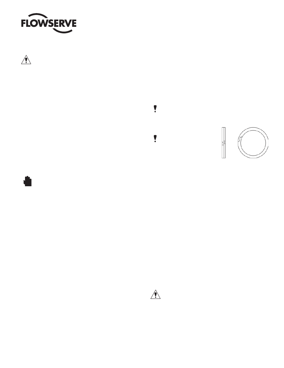
NOTE: Some actuators may
be using a spiral-ring type
shaft clip as shown at right.
To remove this clip, engage the lower end of the ring
with a flat blade screwdriver. Using another flat blade
screwdriver push the top end of the clip in the opposite
direction. As the clip I.D. expands, lift the clip from the
shaft. The installation of a new clip would be the above
steps in reverse and ensuring that the edges of the clip
are properly seated in the shaft groove.
The Rev. R2 model, all sizes and the Rev. R3 through
R7 models, sizes 25 through 42, have an anti-ejection
ring (15J). The anti-ejection ring on Rev. 1, sizes 45–50
consists of a flat washer with a shaft clip. All others are
a one-piece spiral wound ring. This ring does not have
to be removed and may or may not be included in repair
kits.
For Rev. R2 models, remove shaft clip (15F) (not a
reusable part!) (see Note above) and the stainless steel
washer from the shaft. Then remove the top shaft bearing
(15G) and the bottom shaft bearing (15H) by carefully
prying them away from the body.
CAUTION: Both of these bearings may have a projecting
“nib” which locates the bearings to the actuator body. Be
careful not to break off these nibs inside the body when
removing the top and bottom bearings. Note: Top bearing
is marked “Top”. Bottom bearing has a larger ID than the
top bearing.
Next, slide the shaft out through the bottom of the body
and remove the top O-Ring (15D) and the bottom O-Ring
(15E) from the body.
STOP!