Flowserve F39 Series Pneumatic Actuator User Manual
Page 4
4
®
Series F39 Pneumatic Actuator - WCENIM2036-00 05/15
3.5.4 For 2” 59, H71, 82/83, and 2½” 45, 82/83 valves, and
valves 3” and larger with square stem, remove handle
assembly, retaining nut, stop and stop screws. Replace
with valve stem spacer or, if valve has graphite stem
packing, with two Belleville washers (except 8”,10” 82/83
and 10” 51/52), and replace retaining nut.
NOTE: Belleville washers are installed with their larger
diameter sides touching each other. Do not use stem
spacer when Belleville washers are used. Using a wrench
to prevent stem from turning, tighten retaining nut until
stem packing is fully compressed or Bellevilles, if used,
are fully flattened, then back off nut 1/6 turn. Excessive
tightening causes higher torque and shorter seal life.
NOTE: Large valves with V51 high-cycle stem packing
option installed, identified by two Belleville washers
installed and handle assembly, stop and stop screws
removed, and 818/828 series valves, do not require stem
area disassembly.
3.5.5 For 2”–8” 818/828 valves, remove handle assembly,
locking plates and hardware, and stop screw (if any). Do
not remove stop plate (2”–6” sizes) or spacer (8” size).
3.5.6 For ½”–2” 94 valves, remove handle (if any). Do not
remove gland plate or gland bolts.
3.5.7 For 3”–6” 94 and 2”–8” E818/828 valves, remove handle
assembly, stop, and spacer (if any). Do not remove gland
plate or gland bolts.
3.6
Attach bracket/actuator assembly to valve as follows:
3.6.1 Center coupling on valve stem.
3.6.2 Lower mounting bracket/actuator assembly over coupling
and onto valve, making sure that female star drive actu-
ator shaft engages in the correct orientation with the
coupling.
3.6.3 Secure bracket to valve using cap screws and lock-
washers, or bolts and nuts provided in mounting kit.
Tighten securely. For small size top-mount style valves,
bracket nameplate will be to side of valve.
3.6.4 Install set screws (if any) in coupling and tighten securely.
3.6.5 Determine if mode of operation (air to open or close/fail
open or closed) is as desired; if not:
• Air to Open or Close - On all sizes of F39 double-acting
and spring-return actuators, the female drive shaft
is a star drive. This allows selection of either mode of
operation by indexing the coupling (including valve ball
and stem) 90° to the actuator shaft, while keeping the
actuator in an in-line orientation.
• Fail Open or Fail Close - The normal method of mounting
is to have the actuator in line with the pipe line and the
valve and actuator in the “FAIL-CLOSED” (Clockwise to
close) position. “FAIL-OPEN” can be achieved using
the method above but the actuator will then work
as Clockwise to open).
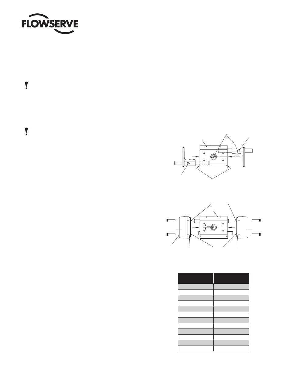
• For “FAIL-OPEN” but with Clockwise to close opera-
tion, the pistons in the actuator will need to be removed
and reassembled from the opposite ends of the
actuator (keeping the guide rods the same sides
relative to the body). This will result in a slight offset
of pinion position on some sizes. See below:
Foolproof pin
location holes
Blank support rod
(without cross hole)
Inlet support rod
(with cross hole)
Label
Position of pinion
flats and groove
(60º approx.)
Bores containing
bearings only
Bores containing
bearings and
0-rings
Foolproof pin
Foolproof pin
Inlet
End Cap
End Cap
Inlet port
Label
#
Limit Stop
Label
Actuator
Size
Pinion Offset
Angle #
05
0°
10
10°
15
2°
20
2°
25
2°
30
2°
33
2°
35
2°
40
0°
42
0°
45
0°
50
12°