Electrical supply, 7 installation of accessories, 8 operation – Flowserve F39 Series Pneumatic Actuator User Manual
Page 6
6
®
Series F39 Pneumatic Actuator - WCENIM2036-00 05/15
6. Electrical Supply
(models with integral solenoid only)
The solenoid coil wattage and required amperage are as
follows:
Watertight and Hazardous Location Solenoids
Voltage
Holding
Amps
Inrush
Amps
Watts
24 VAC 50/60 Hz
.71
1.13
11
120 VAC 50/60 Hz
.14
.23
10
240 VAC 50/60 Hz
.07
.11
10
12 VDC
.81
—
10
24 VDC
.41
—
10
7 INSTALLATION OF ACCESSORIES
For details of installation of accessories refer to the instal-
lation instructions contained in respective accessory kit
8 OPERATION
8.1
Basic Actuator – (N Model)
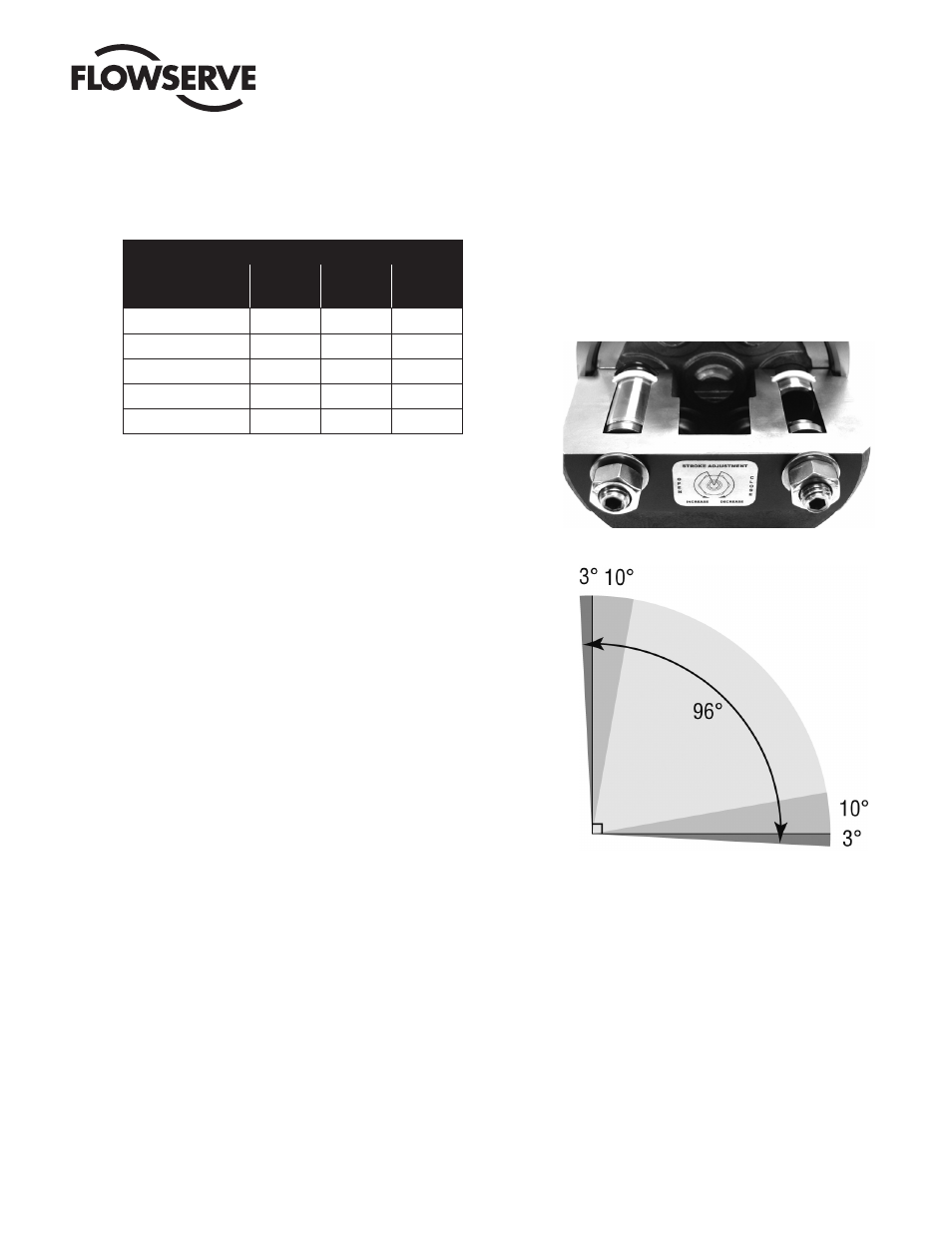
The Series F39 actuator drive shaft rotates through a full
90° segment with approximately 3° overtravel at each
end of travel. Rotation is accomplished by feeding supply
air into the center chamber, forcing the two opposing
pistons apart, resulting in a counter-clockwise rotation of
the drive shaft to the “open” position. For double-acting
actuators, closure is obtained by feeding supply air into
the end cap chambers, which forces the pistons together,
resulting in a clockwise rotation of the drive pinion. For
spring-return actuators, closure is accomplished by
means of springs contained within the end caps which
force the pistons together when the supply air to the
center chamber has been interrupted.
If rotation opposite to that described above is required,
refer to the section on Installation for the proper proce-
dure to reverse the rotation.
The accurate rotation of the actuator pinion is controlled
through the adjustment of two hexagon headed bolts
on the end cap. Each bolt will control either the open
or closing stroke (based on how the actuator has been
orientated on the valve). The adjustment of each bolt
is shown on the end cap. Actuators are factory set to
provide a 90˚ operation. If adjustment needs to be made
the lock nut will need to be backed off, the adjustment
screw rotated to provide correct positioning and the lock
nut retightened. For size 10 to 35 turn screw clockwise
to decrease rotation and counterclockwise to increase
rotation. For size 40 to 50 the reverse applies. It is critical
to retighten to ensure an effective seal of the washer.
Care should be taken to secure travel stop setting when
tightening lock nut.
8.2
Actuator With Factory-Supplied Solenoid
Double-Acting – Air is supplied to the one NPT port on the
bottom of the block. When the solenoid is energized, the
spring-loaded plunger is withdrawn, allowing the supply
air to shift the spool within the block, which opens the
supply path to the center chamber of the actuator. Air
from the end chambers of the actuator is allowed to pass
through the block and exhaust to atmosphere.
When the solenoid is de-energized, the spring-loaded
plunger blocks the flow of air to the center chamber of the
actuator. The supply air now shifts the spool within the