Flowserve F39 Series Pneumatic Actuator User Manual
Page 12
12
®
Series F39 Pneumatic Actuator - WCENIM2036-00 05/15
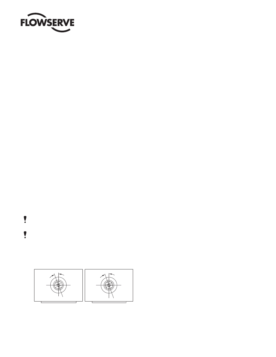
12.2.9 To ensure proper meshing of teeth, move the shaft 15
to 20 degrees counter-clockwise (CCW) from its normal
position when the piston assemblies are located at the
body ends. (See Figure 2.) NOTE: The “normal position”
of the shaft on the 05–20 sizes is when the top flats are
parallel to the main axis of the actuator body. On the 25–
50 sizes the teeth of the shaft will be on the left side of
the actuator when viewed from the ends of actuator. (See
Figure 1.)
12.2.10 With the piston assemblies in the body, gently push each
piston into the body. Turn the top shaft extension clock-
wise (CW). Do not allow the pistons to “cock”.
At the proper point of engagement between the shaft
and piston assemblies, both piston assemblies will move
toward the center of the body when turning the top shaft
extension of the actuator clockwise (CW).
12.2.11 Once the shaft and pistons are properly engaged, ensure
that smooth movement and 90 degree operation can
occur without moving the pistons out of the actuator
body. This is important!
12.2.12 Install O-Ring (15A) into and replace the actuator end
caps, (5 or 5A and 5B), noting that the “foolproof” pin
between the body and end cap mates properly (10–50
sizes only). For sizes 40 to 50 the limit stop end cap must
be assembled first. Once assembled feed the limit stop
bolts through the guide rod and screw into the end cap.
Add the sealing washer and lock nut and then attach the
air inlet end cap.
NOTE: For spring return actuators, see spring installa-
tion section on page 13 before installing end caps.
NOTE: When installing the end cap O-Rings, use a small
amount of a general purpose lubricant, such as petro-
leum jelly, to hold them in place for ease of assembly and
to avoid having them drop down and get pinched.
On Rev. R2 and earlier actuators, be sure O-Ring is
installed in groove on end cap.
12.2.13 VERY IMPORTANT: Install the NEW shaft clip (15F)
into its mating groove on the top shaft extension. (The
removed shaft clip is not to be reused.)
Place the numbered side up on the shaft clip and be
certain the clip is fully seated in its groove. See Note at
bottom of page 10 for installation of spiral-ring type shaft
clip (which newer rebuilding kits will contain).
12.2.14 If solenoid control block was removed:
For size 05 only, place interface gasket (19) onto solenoid
block interface plate (20) and attach securely to body with
three screws (21). Do not apply any grease to gasket.
Place gasket (9) on solenoid control block (7A) or (7B)
(if used) and attach block securely to end cap, or for size
05, the solenoid block interface plate, to obtain a seal at
gasket. NOTE: If fiber gasket is used, work a generous
amount of assembly grease or petroleum jelly into the
gasket prior to assembly (wipe off excess grease). If a
rubber gasket is used, do not apply any grease, it must
be installed dry.
12.2.15 Replace position indicator (17) (if any). See Section 3.6.6.
12.2.16 Mark Rebuild/Accessory Addition Label, if included in
repair kit, and apply to actuator.
05 - 20 F39 Actuator 25 - 50 F39 Actuator
15˚ - 20˚
15˚ - 20˚
Figure 2
Alignment of Shaft at Reassembly
IMPORTANT:
Align gear teeth on the shaft as per Figure 1.