Flowserve F39 Series Pneumatic Actuator User Manual
Page 7
7
®
Series F39 Pneumatic Actuator - WCENIM2036-00 05/15
STOP!
block to a position which opens the supply path to the end
chambers of the actuator. Air from the center chamber
of the actuator is allowed to pass through the block and
exhaust to atmosphere.
The double-acting solenoid assembly is electrically fail-
safe. That is, it will return to its de-energized position
upon electrical failure and cycle the actuator to the closed
position provided the air supply is not interrupted.
Double-acting solenoid assemblies have two inde-
pendently adjustable speed control screws which can be
used to adjust the speed of operation for the opening and/
or closing stroke. If the speed control screws are too tight,
the unit will fail to operate. NOTE: Speed control screws
are shipped from the factory in the full open position.
Spring-Return – Air is supplied to the one NPT port on
the bottom of the block. When the solenoid is energized,
the spring-loaded plunger is withdrawn, which opens the
supply path to the center chamber of the actuator. Air
from the end chambers of the actuator is allowed to pass
directly through the block and exhaust to atmosphere.
When the solenoid is de-energized, the spring-loaded
plunger blocks the flow of air to the center chamber of
the actuator. The springs in the end cap of the actuator,
which were compressed on the opening stroke, now
relax, forcing the air contained in the center chamber
of the actuator to exhaust through its supply port in the
solenoid block. The exhaust air passes through the block
and the solenoid where it exhausts to atmosphere.
When using a spring-return solenoid assembly, only
the speed of the spring stroke is adjustable. This is
accomplished by tightening the set screw contained in
the exhaust nut (shipped separately in envelope) which
mounts directly to the end of the solenoid.
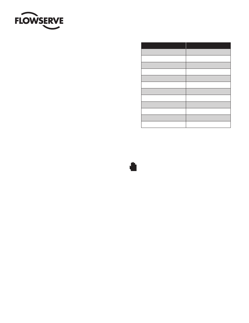
8.3
Standard Stroke Times
Standard stroke times of the Series F39 actuator are
shown in the following table. Times shown are in seconds
and represent average times under 50% load conditions
with an air supply pressure of 80 psig. Times shown are
per stroke for double acting actuators. For spring-return
actuators, the opening stroke times may be slightly
longer; stroke times for the closing (spring) stroke are
dependent upon the number of springs used.
The figures shown below are meant as an indication
of obtainable speeds only. Faster or slower speeds are
obtainable, if required, by using additional control equip-
ment.
Actuator Size
Stroke Time (sec.)
05F39
1
10F39
1
15F39
1
20F39
1
25F39
2–3
30F39
3–4
33F39
4–5
35F39
4–5
40F39
5–6
42F39
6–7
45F39
10–12
50F39
12–14
8.4.
Manual Operation
In the event of air failure, the Series F39 actuator can
be cycled manually. This is accomplished by applying
a wrench to the exposed top shaft of the actuator and
turning it in the desired direction.
WARNING: Care must be taken to ensure that the actuator
is not operated automatically while manual operation is
being performed.
If a routine cycle check is to be performed on a double-
acting actuator equipped with the proper Worcester/
McCANNA solenoid control block, the actuator can be
cycled manually by shifting the spool valve within the
block. This can be done by pushing the red momentary
override button located on the coil housing. The actuator
will cycle to its original position as soon as the manually
applied pressure on the red button is released.