13 spring-return actuator – Flowserve F39 Series Pneumatic Actuator User Manual
Page 13
13
®
Series F39 Pneumatic Actuator - WCENIM2036-00 05/15
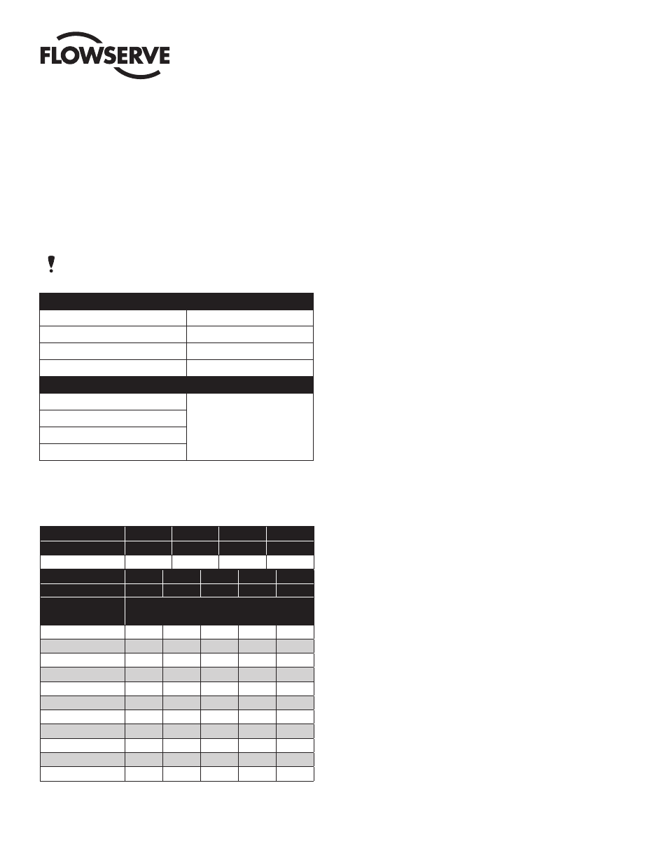
Sizes 10–35 Rev. R2 through R7 and Sizes 40 and 42 Rev. R 2
70 psi - 8 springs - 4 per end cap.
Remove center spring.
60 psi - 8 springs - 4 per end cap.
Remove center spring.
50 psi - 6 springs - 3 per end cap.
Use three on a diagonal.
40 psi - 4 springs - 2 per end cap.
Use two in opposite corners.
Sizes 10–50 Rev. R2 (Except Size 40 and 42)
70 psi - 20 springs - 10 per end cap.
Remove required number of
springs starting in the center.
Remaining springs should be
evenly spaced as possible.
60 psi - 20 springs - 10 per end cap.
50 psi - 16 springs - 8 per end cap.
40 psi - 12 springs - 6 per end cap.
The size 05 spring-return actuator operating at 80 psi has four springs
(two per end cap). For air supplies of 70, 60 or 50, remove inner spring
of each end cap.
Ordering Code
4
5
6
7
( )
Supply Pressure (psi)
40
50
60
70
80
Actuator Size and
Current Rev.
End of Spring Torque (in Lbs)
10 R7
42
63
84
84
104
15 R7
74
112
149
149
186
20 R7
135
212
272
272
339
25 R7
232
348
465
465
581
30 R7
372
558
744
744
929
33 R7
804
1204
1611
1611
2009
35 R7
929
1398
1859
1859
2328
40 R7
1496
2239
2982
2982
3735
42 R7
2593
3885
5177
5177
6469
45 R2
4735
6319
7849
7849
9478
50 R2
7319
9762
12204 12204 14638
Ordering Code
1
1
1
( )
Supply Pressure (psi)
50
60
70
80
05
32
32
32
41
13 SPRING-RETURN ACTUATOR
13.1 When replacing springs in a spring-return actuator,
ensure that the springs are replaced in their identical
position in the end cap from where they were removed.
IMPORTANT: When less than the standard number of
springs are used in each end cap, these springs should
be positioned according to the air supply figures below.
The values listed below are for standard and less than the
standard air pressure as required per the ordering code.
NOTE: Maximum operating pressure does not change.
13.2
If a spring-return actuator is being repaired due to a failed
spring, REPLACE all the springs in this actuator, as well
as any other parts which may have been damaged.
13.3 When replacing the springs in a spring-return actuator,
place the springs in the end cap pocket after thoroughly
lubricating each spring. Be generous with lubricant!
13.4 With the springs pointing up and the end cap on a solid
surface, place the actuator body over the springs and the
proper end cap. (Each end cap can only be mounted to
just one end of the actuator body, as there is a “foolproof”
pin in the end cap, which aligns with a hole in the body.)
13.5
Force the body down and begin by engaging two end cap
screws (5C) by hand through the end cap. Take each end
cap screw up in SMALL and EQUAL turns. Once the end
cap is temporarily secured to the body, turn the actuator
over to its normal position and uniformly take up the four
end cap screws. Uniformly load all the springs to prevent
any spring from buckling.
IMPORTANT: Locating nibs are cast into the Rev. R2 (all
sizes) and the Rev. R3 through R7 (sizes 25 through 42)
actuator piston face. The actuator springs must fit over
these locating nibs on the piston face. Care in following
the above instructions will ensure the proper alignment of
the spring in the actuator body — proper contact with the
piston face and end cap.
13.6 In a similar manner, as written in the previous steps,
replace the springs in the other end of the actuator body.
13.7
On sizes 40 to 50 Rev. R7 only encapsulated springs (pre
compressed) can be used with this design.