6 position indication, 3 combination of contacts (refer to figure 4.2), 1 local position indication – Flowserve L120 Series Limitorque Actuation Systems User Manual
Page 14
Limitorque Actuation Systems L120 Series FCD LMENIM1201-04-AQ – 05/15
14
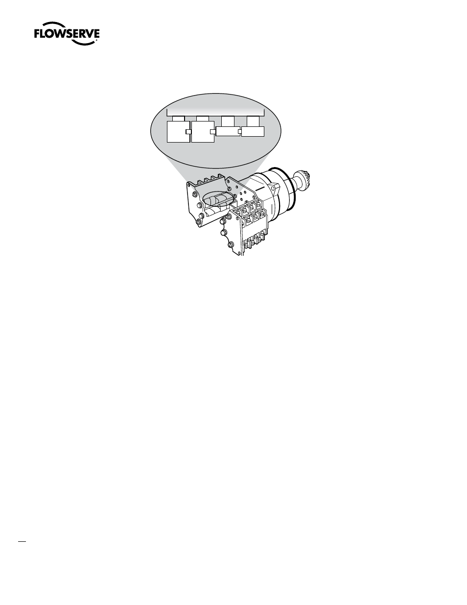
Figure 4.3 – Setting the open and closed contacts
4.5.3 Combination of Contacts (Refer to Figure 4.2)
The rotor segments can be separated and rotated through 90 degrees to give various combinations of
normally open or normally closed contacts to each rotor.
1. Remove Nuts (piece 8) and Fillister Head Machine Screws (piece 5, for a total of two fasteners on
each side of the switch).
2. Remove complete contact assembly from the back plate.
3. Rearrange cams on the camshaft to produce the required combination of contacts.
4. Replace contact assembly on back-plate (ensuring that the registers fit correctly) and secure with
the machine screw and nuts.
5. Set limits according to the procedure above.
4.6 Position Indication
4.6.1 Local position indication
The local dial position indicator is factory-selected to show valve position. The position indicator can
only be adjusted when mounted on the valve.
To set the local position indicator:
1. Disconnect all incoming power and remove Switch Compartment Cover (piece 200 of Figure 5.2).
2. Place the valve in the fully “close” position.
3. Loosen the round head machine screw which holds the pointer in place, move the pointer to the “O”
position, and retighten the screw.
The indicator is now set.
Closed
position
Open
position