7 thrust base disassembly (drive 2 option), 8 stem nut replacement – thrust base applications – Flowserve L120 Series Limitorque Actuation Systems User Manual
Page 30
Limitorque Actuation Systems L120 Series FCD LMENIM1201-04-AQ – 05/15
30
Optional Drive Sleeve
1. Remove the Handwheel (piece 29 of Figure 5.2), Handwheel Cover Plate (piece 33 of Figure 5.2)
and Gasket (piece 34) to provide access to the Elastic Stop Nut (piece 99).
2. Remove the Elastic Stop Nut (piece 99) from the Rod (piece 1). The Torque Nut (piece 95) can now
be removed from the bottom of the Drive Sleeve (piece 25 of Figure 5.2).
3. The Torque Bushing Connector (piece 96) can be removed from the torque nut by removing the
Retaining Ring (piece 98).
6.7 Thrust Base Disassembly (Drive 2 Option)
Piece numbers refer to Figure 6.2.
1. If the Thrust Base (piece 100) option is present, remove the Seal Retainer (piece 102) followed by
Stem Nut (piece 101).
2. Remove the four Hex Head Cap Screws (piece 110) and the Lift Thrust Base from the housing.
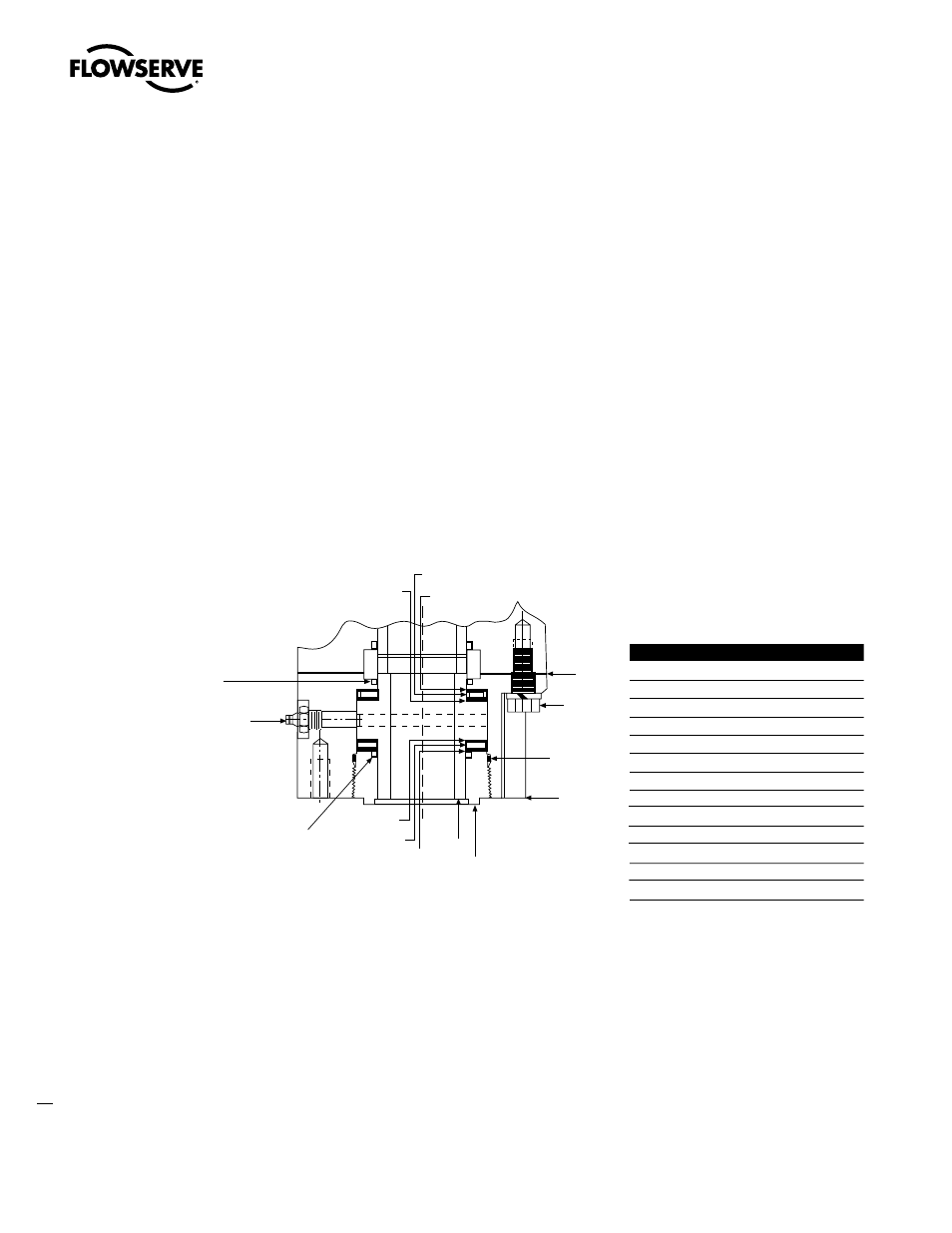
Figure 6.2– L120-10 through 40 thrust base
6.8 Stem Nut Replacement –
Thrust Base Applications
This section is only applicable to thrust base applications. Occasionally the operator stem nut may need
replacing if used in a threaded stem application on rising stem valves.
c
WARNING: Possible Hazardous Voltage. Turn power OFF before disassembling or removing the
actuator from the mounting base. This will prevent accidental start-up during service to the unit.
c
WARNING: Potential High-Pressure Vessel. Before removing or disassembling the actuator, ensure
that the valve or other actuated device is isolated and not under pressure.
107A
109, 112
108
110, 111
106
100
102
101
104
105
103
104
103
105
Piece Quantity
Description
100
1
Base Housing
101
1
Stem Nut
102
1
Seal Retainer
103
2
Needle Bearing
104
2
Thrust Washer
105
2
Thrust Washer
106
1
O-ring Seal
107
1
Quad Ring Seal
107A
1
Quad Ring Seal
108
1
Gasket
109
1
Grease Fitting
110
4
Hex Head Cap Screw
111
4
Lock Washer
112
1
Relief Fitting
107
NOTE: For the L120-10, use the same part number for
piece #107 and 107A. For the L120-20 and L120-40, use
two different part numbers for piece #107 and 107A.