2 remote position indication – Flowserve L120 Series Limitorque Actuation Systems User Manual
Page 15
15
Limitorque Actuation Systems L120 Series FCD LMENIM1201-04-AQ – 05/15
flowserve.com
NOTE: The end-of-travel rotors of the geared limit switch activate “Flip-flop” type indicators. This type of
indicator will require no further setting after the geared limit switch has been adjusted.
4.6.2 Remote Position Indication
The L120 actuator with a position transmitter installed, transmits a 4-20 mA output signal to a remote
position indicator. The transmitter responds to input of a 1K (ohms) potentiometer and can
be powered by 18 VAC or 24 VDC.
NOTE: The pinion has been left disengaged to prevent damaging of rheostat prior to setting the valve.
Set rheostat by turning pinion until the desired reading is obtained. Loosen the hex nut on the back of
the rheostat and slide the rheostat in the direction of the idler pinion until pinions are engaged. Do not
force engagement of the pinions. Retighten hex nut on back of the rheostat. Do not engage pinion until
unit and valve have been set.
To Calibrate Position Transmitter
1. Position the actuator to mid-travel: valve at 50% position.
2. Disconnect the potentiometer wiring harness from the transmitter board and measure the resis-
tance from each end connection to the center connection on the potentiometer.
3. Set the potentiometer to the correct resistance reading. Loosen the set screw that retains the spur
gear on the potentiometer shaft and rotate the shaft until a reading of 500 ohms is achieved.
4. Tighten the set screw and reconnect the wiring harness.
5. Run the actuator fully CLOSED.
6. Calibrate ZERO position by adjusting the zero potentiometer until a 4 mA output signal is read at
terminal +VE and -VE.
7. Run the actuator fully OPEN.
8. Calibrate SPAN position by adjusting the span potentiometer until a 20 mA output signal is read at
terminals +VE and -VE.
9. Repeat steps 5 to 8 and fine-tune as necessary.
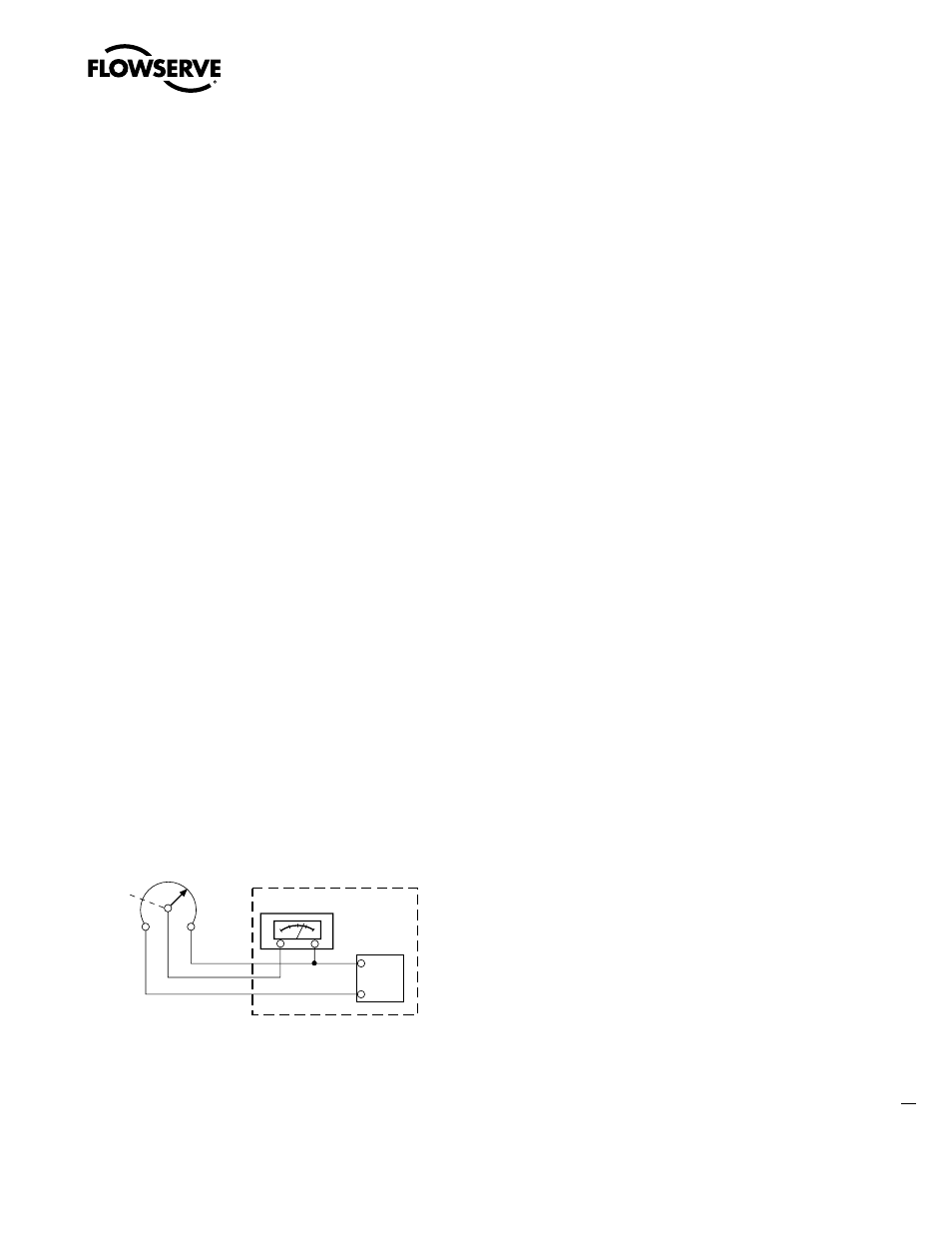
Figure 4.4 – 1000 ohm Potentiometer
DC Power
Supply
-
+
-
+
Receiver
Gearing
1000 ohms
Customer Equipment
Typical Connection for a 1000 ohm Potentiometer