Flowserve L120 Series Limitorque Actuation Systems User Manual
Page 32
Limitorque Actuation Systems L120 Series FCD LMENIM1201-04-AQ – 05/15
32
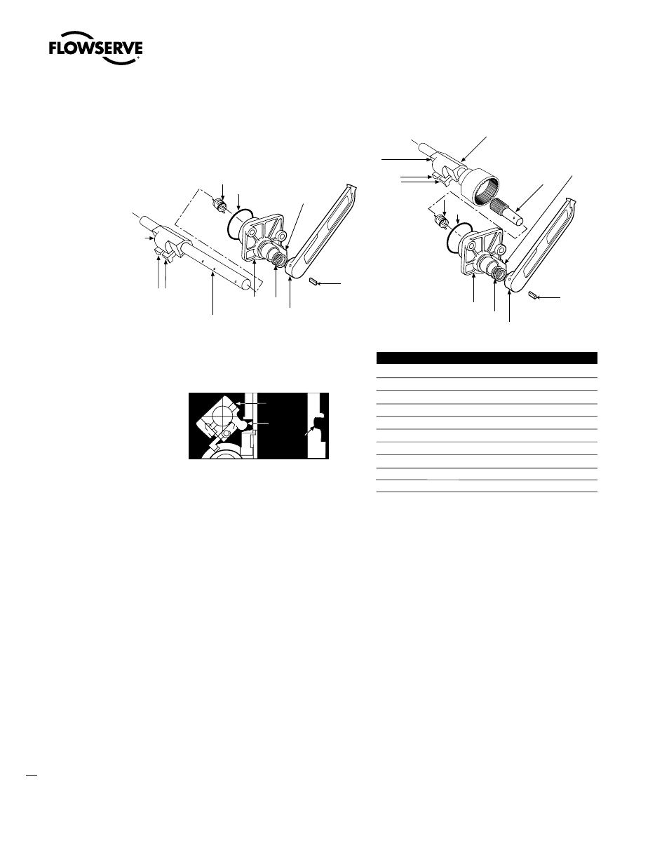
Figure 6.3 – L120-10 through 40 declutch assembly parts breakdown
6.9.1 Declutch Assembly (L120-10)
8. Install Declutch Cap (piece 11) on the Declutch Shaft (piece 7A). Ensure that the return spring is
located correctly in the endcap.
9. Replace Declutch Lever (piece 9) on the shaft with the lever against the stop.
10. While holding the cap steady, rotate the declutch shaft against the spring tension until the holes in
the shaft and lever align.
11. Replace complete assembly in main housing. Ensure that the lug on the Declutch Actuator
(piece 7-1) fits into the groove on the Handwheel Clutch Sleeve (piece 19 of Figure 5.2).
12. Secure the declutch cap.
NOTE: When the declutch lever is disengaged against the declutch stop (motor operation position),
the Declutch Actuator (piece 7-1) should not be in contact with the groove on the Handwheel Clutch
Sleeve (piece 19 of Figure 5.2).
6.9.2 Declutch Assembly (L120-20/40) (Refer to Figure 6.3)
8. Install Declutch Cap (piece 11) on the Declutch Pinion Shaft (piece 12). Ensure that the return
spring is located correctly in the slots.
10
42
11
42/5
12
7
7-2
&
7-3
7-1
Declutch Stop
8
9
7A
L120-10
L120-20/40
9
8
10
42
11
42/5
Declutch Stop
Piece Quantity
Description
7*
1
Declutch Shaft Assembly L120-20/40
7A
1
Declutch Shaft Assembly
7-1
1
Declutch Actuator
7-2 & 7-3 1
Declutch Latch (left & right)
8
1
Declutch Return Spring
9
1
Declutch Lever
10
1
Roll Pin
11
1
Declutch Cap
12*
1
Declutch Input Pinion
42/5
1
O-ring – Declutch
*L120-20/40 only
7-2
&
7-3
7-1
LUG
Declutch
Actuator
Handwheel
Clutch
Sleeve