3 detailed sequence of positioner operations – Flowserve 3400MD Digital Positioner User Manual
Page 10
Logix 3400MD Digital Positioner FCD LGENIM3404-08-AQ –5/15
10
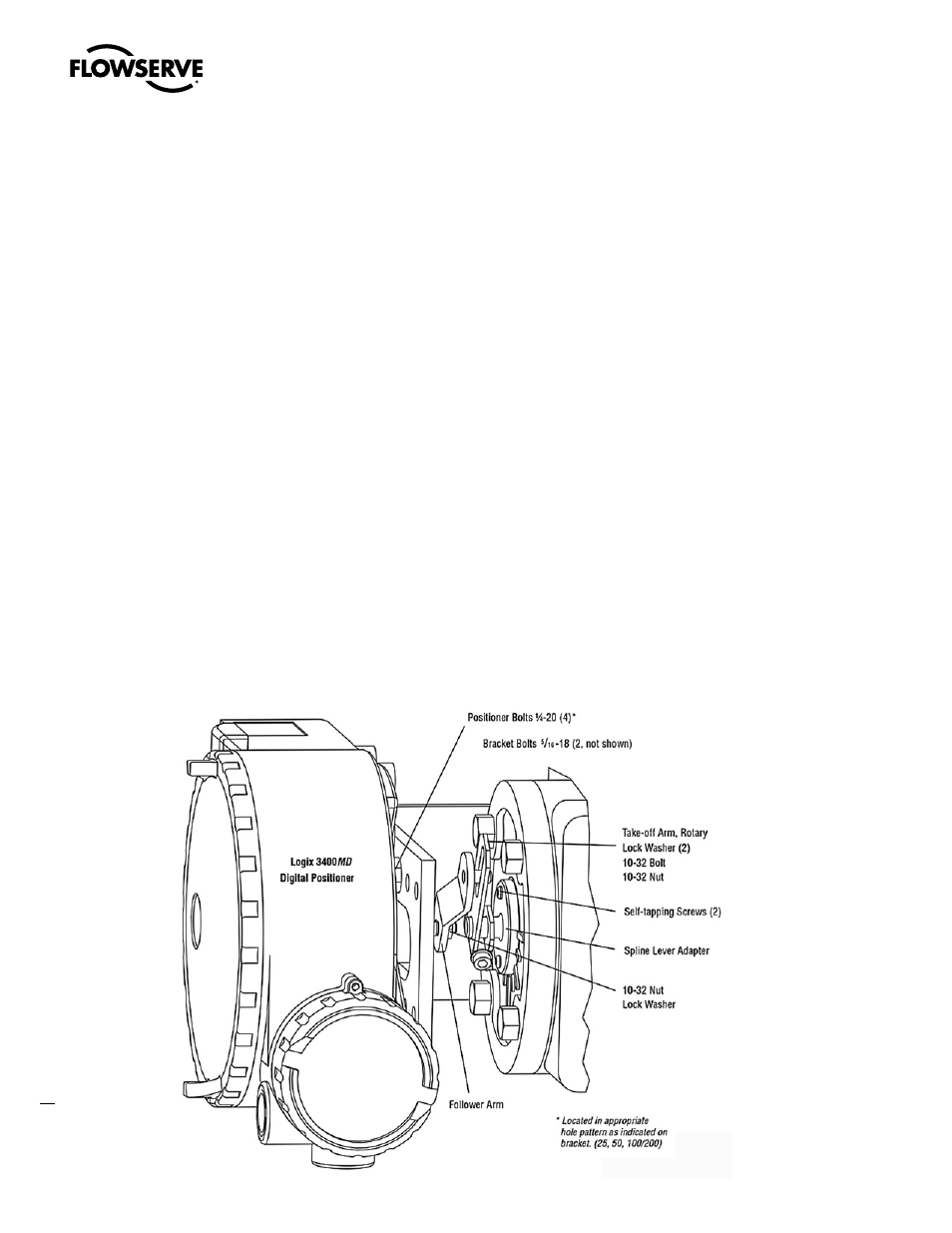
Figure 4: Standard Rotary Mounting
4.3 Detailed Sequence of
Positioner Operations
A more detailed example explains the control function. Assume the
unit is configured as follows:
• Unit is in OOS.
• Custom characterization is disabled (therefore
characterization is Linear).
• No soft limits enabled. No Final Value Cutoff set.
• Valve has zero deviation with a present input command of 50.
• Write to Final_Value to change command.
• Actuator is tubed and positioner is configured air-to-open.
Given these conditions, 50 represents a Command source of 50
percent. Custom characterization is disabled so the Command source
is passed 1:1 to the Control Command. Since zero deviation exists,
the Stem Position is also at 50 percent. With the stem at the desired
position, the spool valve will be at a middle position that balances
the pressures above and below the piston in the actuator. This is
commonly called the null or balanced spool position.Assume the
input signal changes from 50 to 75. The positioner sees this as a
Command source of 75 percent. With Linear characterization, the
Control Command becomes 75 percent. Deviation is the difference
between Control Command and Stem Position : Deviation = 75% -
50% = +25%, where 50 percent is the present stem position. With
this positive deviation, the control algorithm sends a signal to move to
spool up from its present position. As the spool moves up, the supply
air is applied to the bottom of the actuator and air is exhausted from
the top of the actuator. This new pressure differential causes the stem
to start moving towards the desired position of 75 percent. As the
stem moves, the Deviation begins to decrease. The control algorithm
begins to reduce the spool opening. This process continues until the
Deviation goes to zero. At this point, the spool will be back in its null
or balanced position. Stem movement will stop and the desired stem
position is now achieved.
One important parameter has not been discussed to this point: Inner
loop offset. Referring to Figure 2, a number called Inner loop offset
is added to the output of the control algorithm. In order for the spool
to remain in its null or balanced position, the control algorithm must
output a non-zero spool command. This is the purpose of the Inner
loop offset. The value of this number is equivalent to the signal that
must be sent to the spool position control to bring it to a null position
with zero deviation. This parameter is important for proper control
and is optimized and set automatically during stroke calibration.