7 startup, 3 segment compliance voltage, 4 cable requirements – Flowserve 3400MD Digital Positioner User Manual
Page 15: 5 intrinsically safe barriers, 6 dd support
15
Logix 3400MD Digital Positioner FCD LGENIM3404-08-AQ – 5/15
flowserve.com
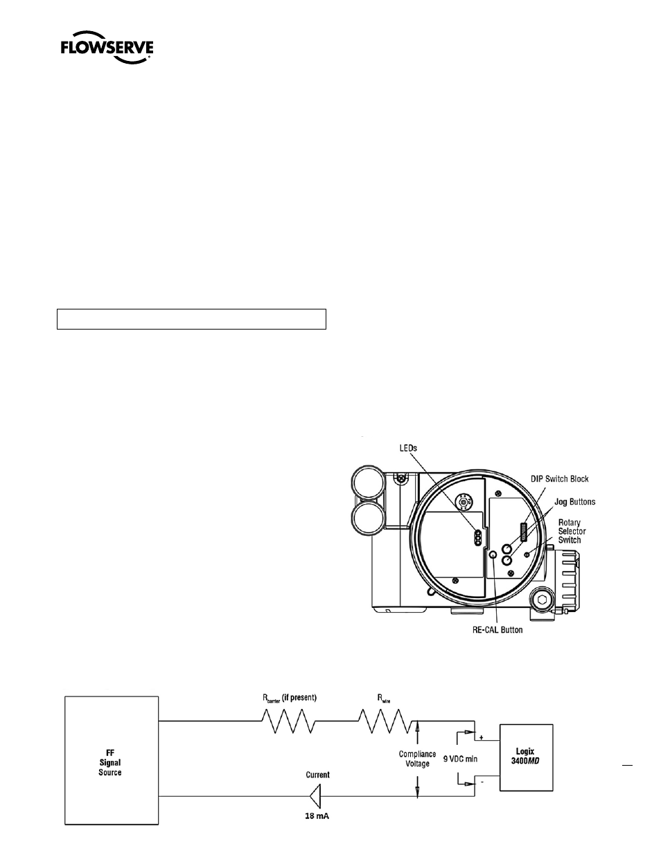
Figure 8: Local User Interface
Figure 7: Compliance Voltage
6.3 Segment Compliance Voltage
(See Figure 7)
Output compliance voltage refers to the voltage limit that can be
provided by the FF source. A FF system consists of the FF source,
wiring resistance, barrier resistance (if present), and the Logix
3400MD positioner voltage. The Logix 3400MD digital positioner
requires that the system allows for a 9.0 VDC drop across the
positioner at minimum segment voltage. The actual voltage at the
terminals varies from 9.0 to 32.0 VDC depending on the FF signal and
ambient temperature.
Determine if the segment will support the Logix 3400MD digital
positioner by performing the following calculation.
Equation 1
Voltage = Compliance Voltage (@ 18 mA) - 18 mA x (R
barrie
r + R
wire
)
The calculated voltage must be greater than 9 VDC in order to safely
support the Logix 3400MD digital positioner.
Example:
DCS Compliance Voltage = 19 VDC
R
barrier
= 25 Ω
R
wire
= 25 Ω
Current
max
= 18 mA
Voltage = 19 VDC – 0.018 A • (300 Ω + 25 Ω) = 13.15VDC
The voltage 13.15 VDC is greater than the required 9.0 VDC; there-
fore, this system will support the Logix 3400MD digital positioner.
6.4 Cable Requirements
The Logix 3400MD digital positioner utilizes the FF protocol. This
communication signal is superimposed on the supply voltage.
FF rated cable should be used. Refer to H1 wiring specification (FF-844).
6.5 Intrinsically Safe Barriers
When selecting an intrinsically safe barrier, make sure the barrier is
FF compatible. Although the barrier will pass the segment voltage
and allow normal positioner operation, if not compatible, it may
prevent FF communication.
6.6 DD Support
The DD for the Logix 3400MD can be downloaded from either the
Flowserve website: www.valvesight.com or the Foundation Fieldbus
website: www.Fieldbus.org.
7 Startup
7.1 Logix 3400MD Local Interface Operation
The Logix 3400MD local user interface (Figure 8) allows the user to
configure the basic operation of the positioner, tune the response,
and calibrate the positioner without additional tools or configurators.
The local interface consists of a RE-CAL button for automatic
zero and span setting, along with two jog buttons (▲ and ▼) for
spanning valve/actuators with no fixed internal stop in the open
position. There is also a DIP switch block containing eight switches.
Six of the switches are for basic configuration settings and two are
for FF options. There is also a rotary selector switch for adjusting the
positioner gain settings. For indication of the operational status or
alarm conditions there are three LEDs on the local user interface.