2 regulator – Flowserve 3400MD Digital Positioner User Manual
Page 39
39
Logix 3400MD Digital Positioner FCD LGENIM3404-08-AQ – 5/15
flowserve.com
27. Install two spool-valve screws and tighten securely with a Phillips
screwdriver (see Figure 14).
28. Slide the spool valve cover assembly over the spool valve until
the tang engages into the housing slot. Install spool valve cover
screw and tighten securely (see Figure 13).
29. Install the plastic board cover. Insert the three retaining screw
through the plastic cover into the threaded boss and tighten
evenly, using a Phillips screwdriver. Do not overtighten (see
Figure 16).
30. Reconnect power and air supply to the positioner and perform a
stroke calibration.
31. Reinstall all covers.
8.2 Regulator
The regulator reduces the pressure of the incoming supply air to a
level that the driver module can use.
Replacing the Regulator
To replace the regulator, refer to Figures 12 and 16 and proceed as
outlined below. The following tools are required:
• Phillips screwdriver
• 1/4” nut driver
c
DANGER: Observe precautions for handling electrostatically
sensitive devices.
1. Make sure valve is bypassed or in a safe condition.
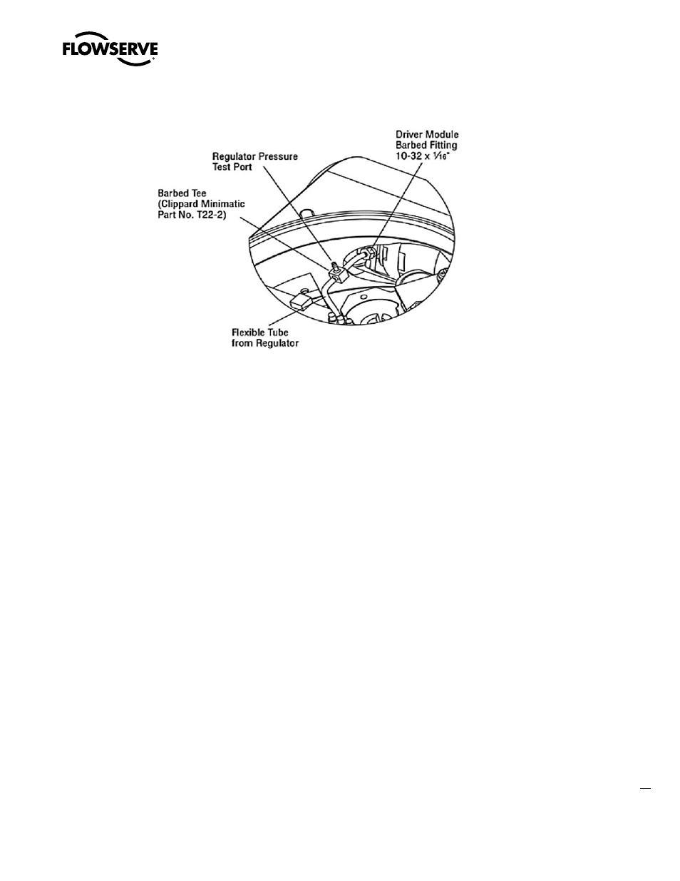
Figure 17: Driver Module Regulator Pressure Check
2. Disconnect the power and air supply to the unit.
3. Remove the main cover.
7. Remove the four screws from the regulator base. Verify that as
regulator is removed, the O-ring and filter remain in the counter-
bore.
8. Remove tubing and barbed fitting from the regulator base.
9. Install barbed fitting and tubing to the new regulator.
10. Verify O-ring and filter are in the counterbore. Install new
regulator using 8-32 x 1/2” screws.
NOTE: Do not mix the regulator with those from older Logix posi-
tioners. Older models contain regulators with different settings
that will not work in the Logix 3400MD model. The regulator
pressure setting is printed on the top of the regulator. The Logix
3400MD regulator is set to 17.4 psig.
11. Reinstall the five wire connections.
12. Install the main PCB into the housing. Insert the retaining screw
through the board into the threaded boss and tighten evenly,
using a Phillips screwdriver. Do not overtighten.
13. Install the plastic board cover. Insert the three retaining screws
through the plastic cover into the threaded boss and tighten
evenly, using a Phillips screwdriver. Do not overtighten (see
Figure 16).
14. Reinstall all covers.