Flowserve LY Series Limitorque User Manual
Page 17
17
Limitorque LY Series: LY 1001, LY 2001 and LY 3001 FCD LMENIM1501-00 – 11/11
flowserve.com
5. Adjust the Limit Switches, Mechanical Stops, and Position Indication Dial following the procedures detailed
in Section 5.7, Limit Switch and Mechanical Stop Settings.
6. Connect the wiring to the terminal strips provided on the actuator. Refer to the wiring diagram supplied
with the actuator. “Fork-type” terminal connections are recommended.
7. Insert a Conduit Pipe Plug in the unused conduit entrance if the wiring that enters the actuator uses only
one conduit entrance.
NOTE:
a. Explosionproof actuators require approved “sealing fittings” installed in accordance with the
National Electric Code.
b. Submersible actuators require an approved “sealing fitting” in order to keep water from entering
the actuator.
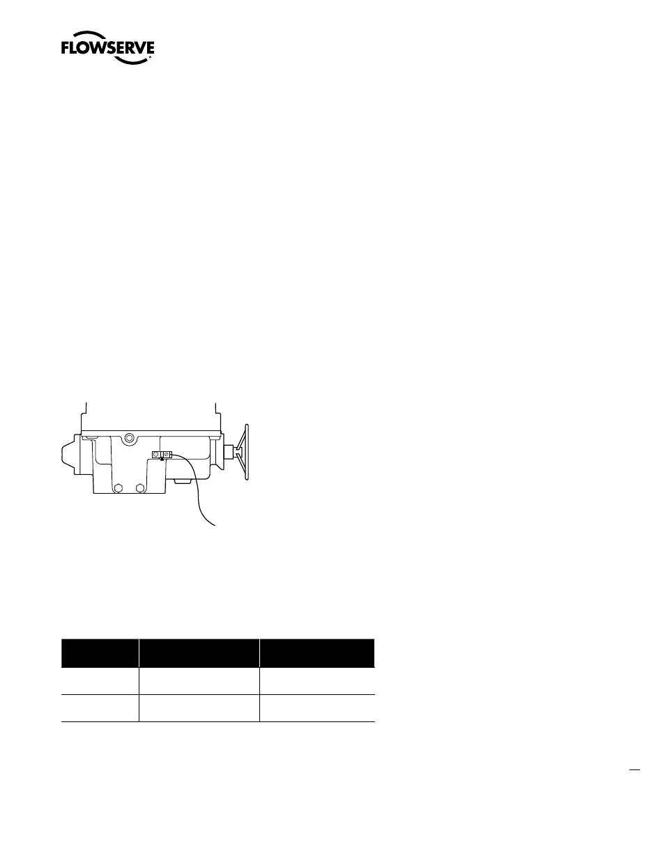
8. Attach grounding wire to Grounding Lug (piece #141).
9. Verify motor rotation direction to ensure that the limit switch is wired properly for intended operation. (See
Section 6.2, Verify Correct Motor Rotation (Phasing) and OPEN/CLOSE Pushbutton Operation.)
Figure 5.5 – Grounding Lug Location
10. Reinstall Control Cover (piece #3).
NOTE: Submersible actuators require tightening the Control Cover Bolts and Integral Control Cover Bolts to
a specified torque in order to maintain submersibility. (See Table 5.4 for specific torque settings.)
Table 5.4 – LY Control Cover and Integral Control Cover Bolt Sizes and Torques
Unit Type
Control Cover
Integral Compartment
LY 1001
M8 - 10 to 15 ft-lb
M10 - 15 to 20 ft-lb
LY 2001/3001
M12 - 20 to 25 ft-lb
M10 - 15 to 20 ft-lb
Unit is now ready for electrical operation.
#141 Grounding Lug
To earth ground