Figure 6.3 – standard actuator/single-phase, Ly compartment, Valve shown in full open position – Flowserve LY Series Limitorque User Manual
Page 33
33
Limitorque LY Series: LY 1001, LY 2001 and LY 3001 FCD LMENIM1501-00 – 11/11
flowserve.com
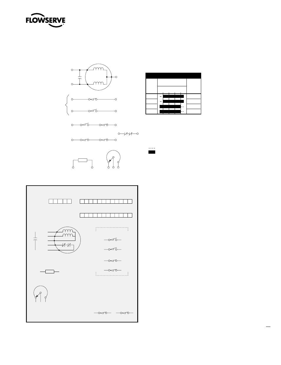
Figure 6.3 – Standard Actuator/Single-Phase
T2
T1
1 ph
MOTO R
T3
CAP
T2
T1
(P)
(P)
P3
P2
P1
5
9
5C
9C
17
18
17C
18C
8
4
INDICATION
TS18
TS17
LS5
LS9
LS8
LS4
CLOSE CIRCUIT
OPEN CIRCUIT
POT
(OPTIONAL)
L2
L1
HTR
LY COMPARTMENT
9
17C
9C
8
5
5C
18C
4
TOP
BOTTOM
LS4
1ph
MOTOR
T1
T2
T2
T1
CAP.
LS8
LS5
LS9
TS17
17C
17
TS18
18C
18
L2
L1
HTR
P1 P2 P3
CLOSE
OPEN
POT
(OPTIONAL)
TH.OL
T3
P3
9C
L1
T2
17
L2
8
P2
P1
9
T1
T3
5
5C
4
CL2
22
CL2
22
CL2
TH.OL
LEGEND
HTR —Space heater (LY COMPT.)
POT —Slidewire transmitter (optional)
(See certification sheet if supplied)
TH. OL —Thermal overload (internal)
TS18 —Opening torque switch interrupts
control circuit if mechanical overload
occurs during opening cycle.
TS17 —Closing torque switch interrupts
control circuit if mechanical overload
occurs during closing cycle.
NOTES
1. Open contact
2. Close contact
3. All limit switch trip points
are fully adjustable.
Limit Switch Contact Development
LIMIT
SWITCH
CONTACT
4
5
8
9
VALVE POSITION
FULL
OPEN
FULL
CLOSE
FUNCTION
OPEN LIMIT
INDICATION
CLOSED LIMIT
INDICATION
Valve shown in full open position
Note: Refer to certified data
for construction purposes
16-476-1630-2C.
22
18