Flowserve LY Series Limitorque User Manual
Page 20
Limitorque LY Series: LY 1001, LY 2001 and LY 3001 FCD LMENIM1501-00 – 11/11
20
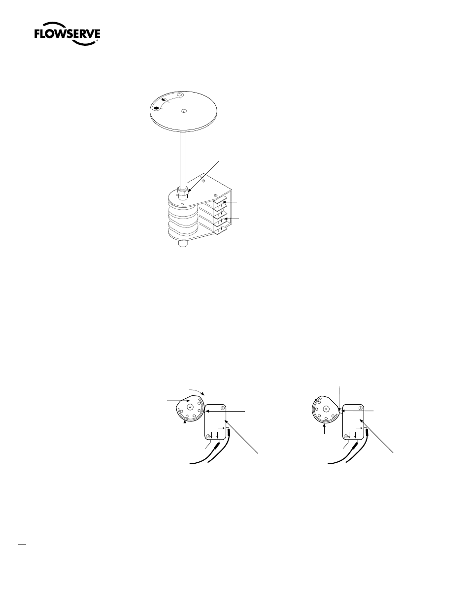
Figure 5.7 – Limit Switch Setting Nut
4. Rotate the CLOSE Limit Cam CW through the high side to the trip point until the Switch Plunger is
released. This causes the N.O. (normally open) contact to open.
NOTE:
There will be no electrical continuity at the trip point when measuring with an ohmmeter
between the common lead and the N.O. lead. You may also hear a faint “click” at the trip point.
NOTE:
During actuator operation, when the Switch Plunger trips, the N.O. contact is released,
causing the Limit Switch to stop the actuator in the CLOSED position.
Figure 5.8 – Setting CLOSE Limit Cam
5. Retighten Setting Nut (piece #7-10).
PERCENT
OPEN
0
50 100
Limitorque
7-10
Standard OPEN
Microswitch location
Standard CLOSE
Microswitch location
CLOSE microswitch
position while valve
is traveling from OPEN
toward the CLOSED
position
High Side
Rotate CW to
reach CLOSE
Trip Point
CLOSE
Limit Cam
CLOSE microswitch
position when valve
has reached the CLOSED
position and microswitch
has tripped
High Side
CLOSE
Trip Point
position
(“click”)
CLOSE
Limit Cam
Switch
Plunger
Switch Plunger
NO
NC
COM
NO
NC
COM