9 mechanical stops – Flowserve LY Series Limitorque User Manual
Page 22
Limitorque LY Series: LY 1001, LY 2001 and LY 3001 FCD LMENIM1501-00 – 11/11
22
5.9 Mechanical Stops
5.9.1 Setting the CLOSED Mechanical Stop on the LY 1001
Table 5.5 – Mechanical Stop Set Screws
Unit Type
Mechanical Stop Set Screw Size
Set Screw Size
LY 1001
3/8-16 x 1.25"
3/8-16 x 0.375"
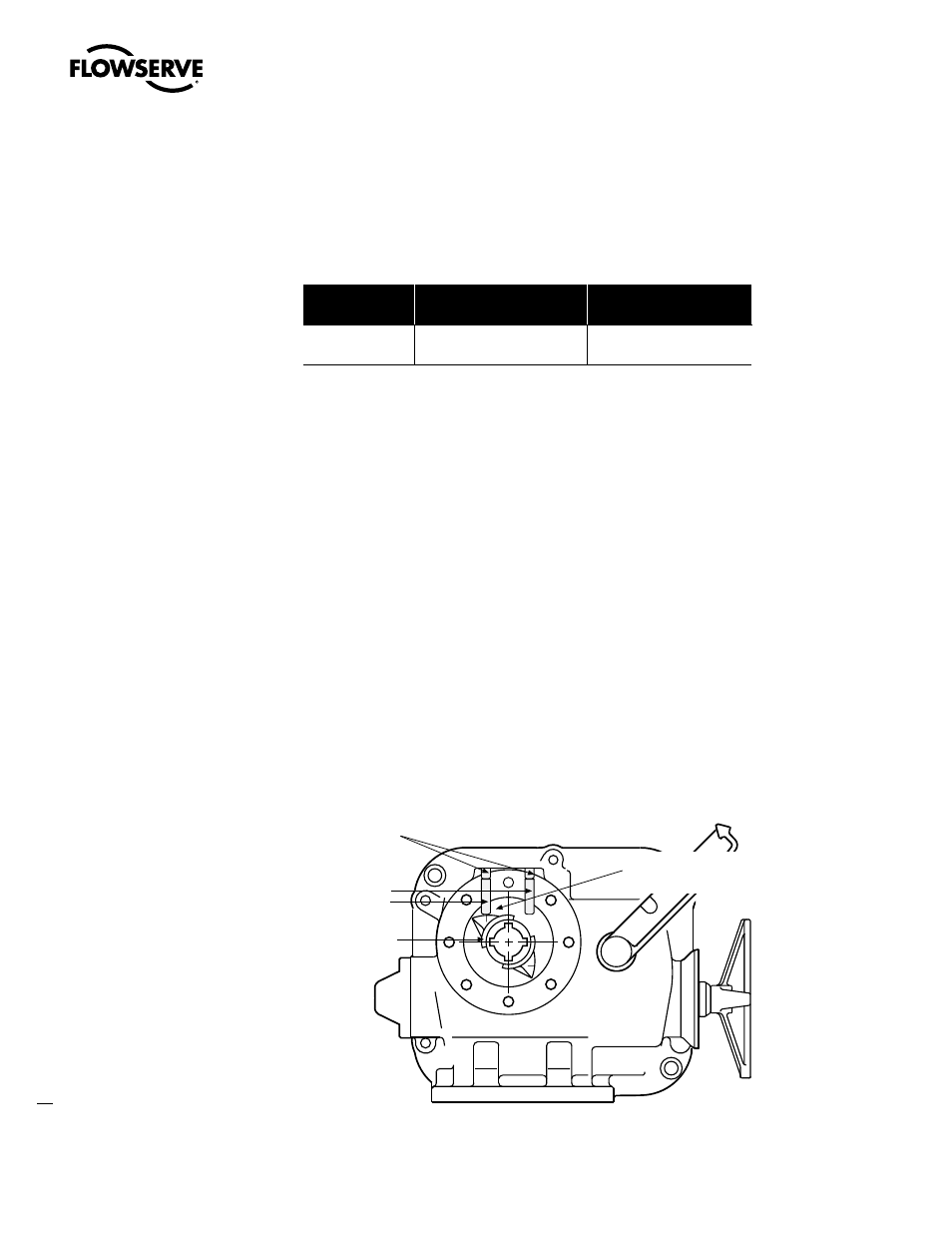
Piece numbers refer to Figure 5.10.
1. Set CLOSE Mechanical Stop Set Screw (piece #58) by removing the Set Screw (piece #59).
2. Using the Handwheel, turn the valve to the CLOSE position. Make sure the valve is fully seated
before setting the mechanical stop.
3. Rotate Mechanical Stop Set Screw (piece #58) in the CW direction until contact with the Torque Nut
(piece #32) occurs. (See Figure 5.9.)
4. Back-off Mechanical Stop Set Screw (CCW direction) approximately 11/2 turns.
5. Reinstall Set Screw (piece #59).
6. Manually operate the actuator through the close limit to assure setting is correct.
NOTE:
The Mechanical Stops are intended to protect the equipment from overtravel if a Limit Switch
fails. The valve should not torque-out against the Mechanical Stop Set Screw during normal OPEN/
CLOSE cycles.
Figure 5.10 – Mechanical Stop Set Screw Adjusted to Torque Nut Contact Point on LY 1001
#59 Set Screw
#58 Mechanical
Stop Set Screw
#32 Torque Nut
Torque Nut &
Mechanical Stop Screw
positioned at contact point
CCW to Open
Mechanical Stop
Set Screws
OPEN CLOSED
LY 1001 Bottom View