Worcester actuation systems – Flowserve DRC-17 User Manual
Page 12
12
DataFlo Digital Electronic Remote Controller DRC17
WCAIM2058
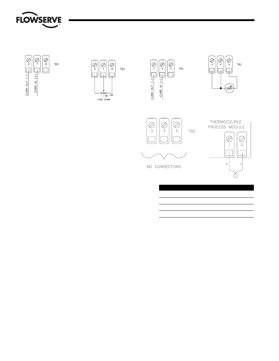
3.3.2 Wiring for a Potentiometer Setpoint
(DRC17 – K – x – x – xxx)
Refer to Figure 8 and connect one side of a potentiometer
to TB2 location 6 in the DRC enclosure. The side chosen
should be the direction the wiper will move to decrease
the setpoint (generally counterclockwise).
Connect the other side of the potentiometer to TB2
location 7 in the DRC enclosure. This side should be the
direction the wiper will move to increase the setpoint
(generally clockwise).
Connect the wiper of the potentiometer to TB2 location 8
in the DRC enclosure.
3.3.3 Wiring for an Analog Current Process
(DRC17 – x – 4 – x – xxx)
Refer to Figure 9 and connect the process positive current
lead to TB2 location 4 in the DRC enclosure.
Connect the process negative current lead to TB2 location
3 in the DRC enclosure.
Location 5 has no connection.
3.3.4 Wiring for an RTD Process (DRC17 – x – R – x – xxx)
Refer to Figure 10 and connect the BLACK return lead of a
100-ohm platinum RTD to TB2 location 3.
Connect the BLACK sense lead of the RTD to TB2
location 4.
Connect the RED source lead of the RTD to TB2
location 5.
3.3.5 Wiring for a Thermocouple Process
(DRC17 – x – J (K,T, or E) – x – xxx)
The wiring of the thermocouple to the process module
must be done as shown below for the type of
thermocouple selected. The polarity of the wires is critical
for proper operation. The thermocouple module is located
on the component side of the microcontroller board
mounted to the front door of the DRC.
Type
Term 1 (+)
Term 2 (–)
J
Fe
C
K
Ni-Cr
Ni-Al
E
Ni-Cr
C
T
Cu
C
Where: FE = Iron
C = Constantan
Ni-Cr = Nickel-Chromium (Chromel)
Ni-Al = Nickel-Aluminum (Alumel)
Cu = Copper
Using the table and illustrations above, connect the
positive thermocouple lead directly to the thermocouple
process module connector TB3 at location 1. Do not
make copper wire splices or extensions to this wire — it
must be directly attached.
Similarly, connect the negative thermocouple lead directly
to the thermocouple process module connector TB3 at
location 2.
There are no connections to TB2 in locations 3 through 5.
Flow Control
Worcester Actuation Systems
Figure 7
Current Setpoint Connection
Figure 9
Analog Current Process
Connection
Figure 10
RTD Process Connection
Figure 8
Potentiometer Setpoint
Connection
Figure 11