Worcester actuation systems – Flowserve DRC-17 User Manual
Page 13
WCAIM2058
DataFlo Digital Electronic Remote Controller DRC17
13
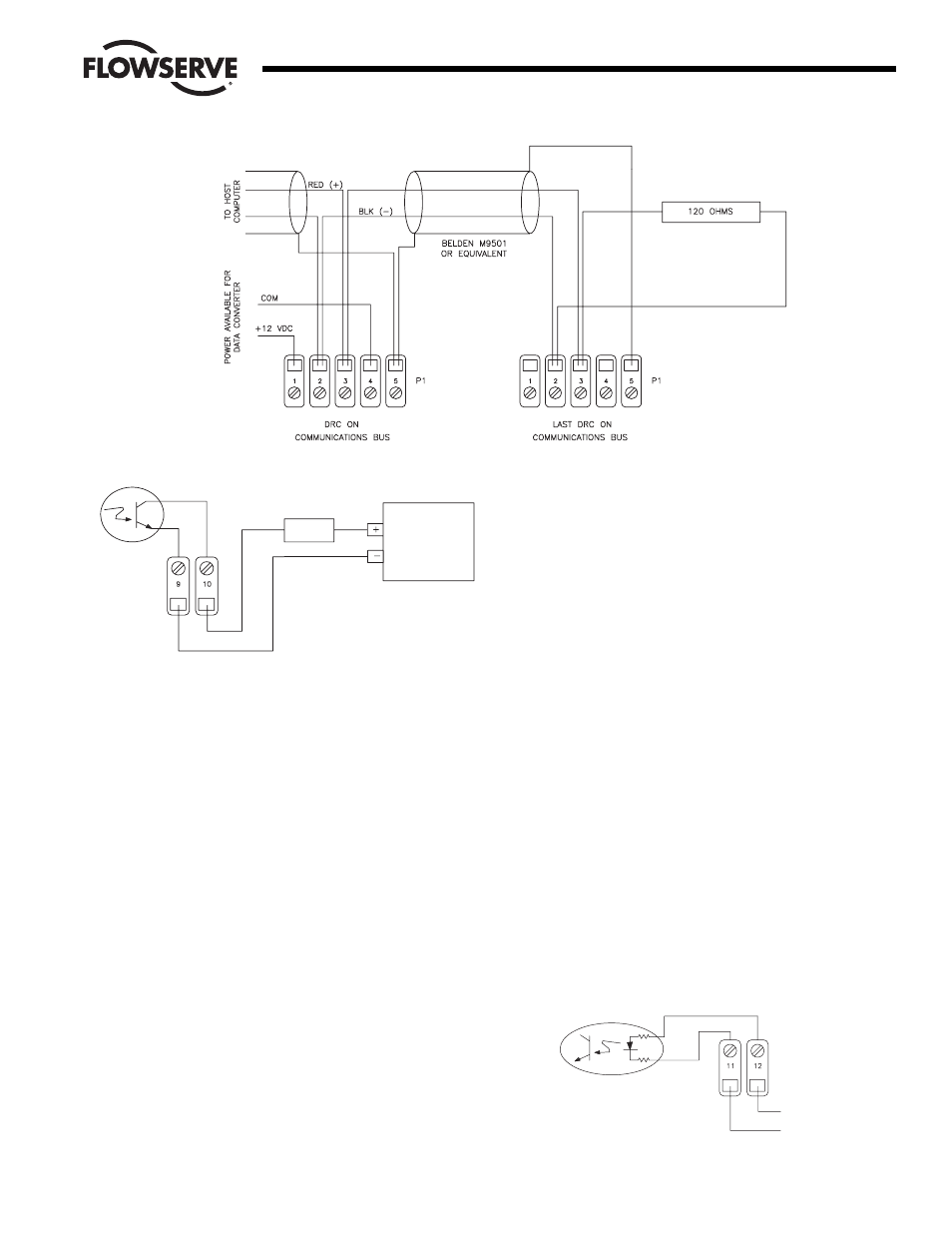
3.3.6 Serial Communications Wiring
In these steps, the DRC is shown attached to an RS-485
serial communications bus with another DRC and a host
controller. The last DRC on the communications bus must
have a terminating resistor installed as shown.
Attach the RED positive communications wire to P1 at
location 3. If another DRC is on the bus, its positive
communication wire should also be attached here. If this
is the last DRC on the bus, attach one side of a 120-ohm
resistor at this location as shown below.
Attach the BLACK negative communications wire to P1 at
location 2. If another DRC is on the bus, its negative
communication wire should also be attached here. If this
is the last DRC on the bus, attach the other side of the
120-ohm resistor at this location as shown.
Attach the drain wire shield(s) to P1 at location 5. This
location provides a high resistance and capacitive
reactance to chassis ground.
P1 location 1 provides +12 VDC at 100 mA (maximum)
power supply for a data converter. P1 location 4 is the
common for this power supply. A likely device would be
an RS-232 to RS-485 converter.
3.3.7 Alarm Output Wiring
The alarm output of the DRC consists of an optically-
isolated NPN transistor that can be used to close the
circuit for an light, buzzer, or other alarm. This circuit can
also be used to signal other equipment. The isolated
transistor can handle voltages up to 25 volts and a
maximum continuous current of 100 mA. The output
circuit is shown below connected to a power source and
load.
Connect the negative lead of a power source to TB2
location 9 (transistor emitter).
Connect the positive lead of the power source to one side
of a load.
Connect the other side of the load to TB2 location 10
(transistor collector).
3.3.8 Position/Control Select Wiring
This wiring allows the DRC to become a simple valve
positioner controlled by the setpoint input. Activating this
input will cause the DRC to discontinue controlling and
begin positioning. The input is an optically-isolated
transistor designed to receive a 12 to 24-volt signal to
activate positioning as shown in Figure 14.
Attach the positive lead from a 24-volt signal to TB2
location 12.
Attach the common lead from the signal to TB2
location 11.
Flow Control
Worcester Actuation Systems
Figure 12
INTERNAL DRIVER
REPRESENTATION
LOAD
+V POWER
SUPPLY
(5–24VDC)
TB2
INTERNAL CIRCUIT
REPRESENTATION
+12 TO +24 VOLT
COM (GND)
TB2
Figure 14
Figure 13