0 operation of the digital controller, Worcester actuation systems – Flowserve DRC-17 User Manual
Page 14
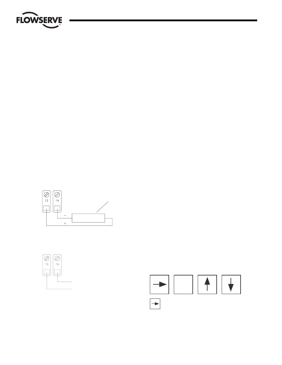
3.3.9 Position Feedback Output Wiring (applies to optional
module #19226 only)
This output provides a current proportional to the position
of the valve shaft. Depending on the output current
parameter setting, the output will be either 4 mA or 0 mA
at 0% position. The output will be 20 mA at 100%. The
voltage for this current source is provided by the DRC
circuitry. The load resistance should be less than 350
ohms. A typical monitoring circuit is shown in Figure 15.
Attach the positive monitoring lead to TB2 location 13.
Attach the negative monitoring lead to TB2 location 14.
3.3.10 Utility Voltage Source
The DRC provides a 5-volt power source to be used by
external devices. This output is +5 volts and can supply
up to 50 mA. Connect to the supply as shown in
Figure 16.
3.3.11 Spare Connection Locations
The DRC provides 8 uncommitted connection points
labeled in pairs as “LS1” through “LS4”. These locations
provide a convenient way of connecting to actuator
signals. These locations may be defined by the customer
and do not have any connection to DRC electronics.
4.0 Operation of the Digital Controller
4.1 General Operation
When power is applied to the DRC, it enters the Run Mode and
begins controlling the process. The DRC achieves control by
comparing the setpoint to the process. As the setpoint changes,
or as outside factors change the process value, the DRC will
adjust valve position to maintain control. Several parameters can
be set to specify the behavior of the controller — the way it
controls the process. The front-panel display and keypad are
used to enter and view data. Using the keypad, the operator can
also change the mode of operation.
The DRC controls the process according to the setting of various
parameters. Parameters are changed in the Program Mode,
described in this section.
The DRC circuitry is calibrated from the factory for accurate
operation. If it becomes necessary to recalibrate the circuitry it
can be done in the Calibration Mode, described in this section.
The DRC normally receives the setpoint signal from an external
source. However, the DRC can also operate with an operator-
entered setpoint by using the Manual Setpoint Mode, described
in this section.
Sometimes it is desirable to suspend controlling and move the
valve to a known position. This can be achieved in the Manual
Position Mode, described in this section. Positioning can also be
achieved by activating a special input that causes the DRC to
become a positioner, using the analog setpoint input to specify
valve position (see External Positioning in this section).
As the DRC controls the process, various alarm conditions can
occur. The DRC contains a circuit that will provide an optically-
isolated alarm output that will activate when any alarm occurs.
This output can be used simply for notification or as a signal to
other processes. Parameters can be programmed to take an
action when certain alarms occur. The alarm state can be viewed
on the DRC display.
An optional current output module can be used to indicate shaft
position. A programmable parameter can be set to specify the
current range (4 to 20 mA or 0 to 20 mA).
4.2 The DRC Keypad
The keypad is used to enter data and move between displays.
The layout of the keypad is shown below.
This key is used to return to the process value
display of the Run Mode from any of the other modes.
While editing a parameter in other modes, this key will
abort editing (and not exit the mode).
ENT
14
DataFlo Digital Electronic Remote Controller DRC17
WCAIM2058
Flow Control
Worcester Actuation Systems
SENSING RESISTOR
SHOULD BE LESS
THAN 250 OHMS
221 OHMS 1%
TB2
+5 VDC
COMMON
TB
Figure 15
Figure 16