0 general, Worcester actuation systems – Flowserve DRC-17 User Manual
Page 3
1.0 General
The Worcester Actuation Systems Dataflo Remote Controller (DRC17)
was designed for use with the Worcester Series 75 electric actuators.
However, it may also be used with other actuators or electrically
operated rotary devices, provided the specified load parameters given
in Part 5.5 are not exceeded.
1.1 Important Items
PLEASE READ THIS SECTION
1.1.1 Sensitivity to Electrical Noise
The Dataflo Remote Controller (hereafter referred to as
the DRC) is sensitive to electrical noise on signal, process
and power supply lines. The DRC can also be affected by
radiated electrical noise. For maximum controller
sensitivity, the electrical noise level should be as low as
possible. Follow the installation and calibration guidelines
carefully and use shielded cable as noted in the paragraph
below.
Shielded wire should be used for all setpoint and process
signal input circuit wiring regardless of length. The
wiring from the feedback potentiometer and the control
signals between the actuator and the DRC enclosure
should be in a shielded cable as shown in section 3.0. If
multiple cables are used, their individual shields must be
attached together inside the actuator and connected as
shown for the one shield. A shield should never be used
as one of the signal wires. Shields for setpoint and
process signals should be grounded at their source and
not connected at the DRC.
NOTE: ALL WIRING TO TERMINAL STRIPS SHOULD BE
INSERTED ONLY TO MID-POINT OF TERMINAL STRIP.
For 240 VAC DRC only, limit switches do not directly
control the motor(s). Therefore, the actuator will not stop
when the limit switches trip. Use care not to drive the
actuator past its normal limits.
1.1.2 Fuses and Input Currents
The Setpoint input circuit is protected with a fuse (F1)
located on the microcontroller board inside the DRC
enclosure. The fuse is used to protect the input circuit
from excessively high current. The fuse is a
¹⁄₁₆ Amp
(about 62 mA) fast-acting fuse (Littlefuse PICO II or
equivalent). Although this fuse limits excessively high
currents, care should be taken to prevent current values
that are less than 62 mA but above 20 mA. High current
that would not cause the fuse to open might cause
excessive heating of the sense resistor. This fuse is
mounted in a socket holder for easy replacement.
The power supply circuit is protected with a fuse (F1)
located on the DRC Power Supply Board. This fuse is
¹⁄₄
Amp slow-acting fuse used to protect the power supply
from excessive current. If this fuse opens, the DRC
should be returned to Flowserve for service.
If the Analog Process Module is used, it also contains a
fuse for protection. The fuse (F1) is the same as that
described for the Setpoint circuit and is located on the
Analog Process Module. Although this fuse limits
excessively high currents, care should be taken to prevent
current values that are less than 62 mA but above 20 mA.
High current that would not cause the fuse to open might
cause excessive heating of the sense resistor. This fuse is
mounted in a socket holder for easy replacement.
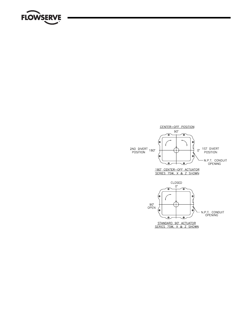
1.1.3 Valve Actuator Configurations
The DRC electronics are designed to control the valve
actuator in 90° quadrants only, however with alternate
feedback potentiometer gearing, 180° of rotation is also
available. The number of quadrants over which the board
will control is determined by the number of teeth on the
feedback potentiometer pinion gear.
Quadrants of Operation
1.1.4 Position Feedback Potentiometer Calibration
Quite often, units received for repair are totally functional
except the feedback potentiometer (pot) is out of
calibration. It is very important that the feedback pot be
properly calibrated for correct operation of the DRC. It is
also very important that the actuator shaft not be rotated
out of the quadrant for which the feedback pot has been
calibrated. Always check the feedback pot calibration first
if calibration problems are encountered. See paragraph
6.5.6 in the troubleshooting section.
WCAIM2058
DataFlo Digital Electronic Remote Controller DRC17
3
Flow Control
Worcester Actuation Systems