Measuring chassis grounding resistance – Fluke Biomedical ESA180 User Manual
Page 29
Operation, Maintenance, and Service
Measuring Chassis Grounding Resistance
2
2-7
Measuring Chassis Grounding Resistance
Note
This test is only applicable to devices utilizing three-wire (grounded)
power cords.
Ground Wire Resistance [R
G
] (grounding resistance) is the resistance from the
device's conductive "grounded" chassis to the grounding terminal on the
receptacle into which it is plugged. The resistance is largely composed of the
GROUND
wire in the power cable and is directly proportional to its length.
Use the following steps to measure chassis grounding resistance:
1. Connect the standard cable supplied with unit that has a black cable with
the clamp with black insulation to the CHASSIS connector on the front
panel of the Analyzer.
2. Clamp the clip of the cable to the DUT's exposed chassis or the enclosure,
if conductive. Resistance is measured between the clip on the black
chassis cable and the grounding pin receptacle of the Analyzer.
Take care to ensure that bare metal is reached and that both jaws of the
clip are in contact with the chassis. Metal labels or incidental conductive
hardware should not be used for this test.
If a non-conducting enclosure is used and no chassis is readily accessible,
a safety ground terminal can be used.
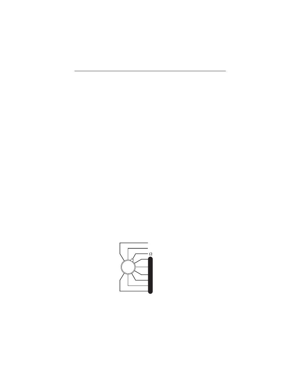
3. Once connection is made, rotate the FUNCTION switch to
Ω
- RESISTANCE and read its value directly in ohms to 19.99
Ω
.
V
V
A
A
µA
µA
L
E
A
K
A
G
E
- CURRENT
- CURRENT
- RESISTANCE
- RESISTANCE
- GROUND
- GROUND
- CHASSIS
- CHASSIS
- LEAD -GND
- LEAD -GND
- LEAD -LEAD
- LEAD -LEAD
- LEAD ISO
- LEAD ISO
- DUAL
- DUAL
- LINE VOLTS
- LINE VOLTS
- CURRENT
- CURRENT
- RESISTANCE
- RESISTANCE
- GROUND
- GROUND
- CHASSIS
- CHASSIS
- LEAD -GND
- LEAD -GND
- LEAD -LEAD
- LEAD -LEAD
- LEAD ISO
- LEAD ISO
- DUAL
- DUAL
fat05.eps