Fronius Selectiva Plus (three-phase) User Manual
Page 41
11
EN
LocalNet connec-
tion socket
A standardised 10-pin connection socket is available for the LocalNet option. A remote
display or a relay board can be connected to the LocalNet connection socket.
(1)
(2)
X 6/1
X 6/2
N
L
4 A
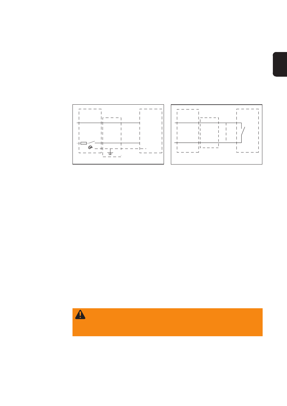
Fig. 7 Electrolyte circulation wiring diagram
X 6/PE
Fig. 8 Electrolyte circulation error output wiring
diagram
(1)
(2)
X 7/1
X 7/4
(1) Charger
(2) Pump
Electrolyte
circulation option
(continued)
Additional option, ERROR 14 error output:
Error detection (air pressure monitoring) is optionally available for electrolyte circulation.
The charger multifunction panel displays an error message („Error 14“) if electrolyte
circulation fails.
Important! If the electrolyte circulation pump does not have an optional error output:
-
Connect contacts X7/1 and X7/4 together.
If electrolyte circulation pump does have an optional error output:
-
Connect no-voltage contact (relay/normally open contact) to contacts X 7/1 and X 7/4
Charge parameter switching: if electrolyte circulation fails, the charger alone ensures
sufficient mixing of the electrolyte.
The relay board is used to analyse
- basic information about the operating status of the charger
- the SOC of the connected battery
The analysis lines can be connected to a PLC or a process control system.
The connections for the analysis lines are like no-voltage change-over contacts with a
common root. The following information can be transferred:
- Battery charging/not charging
- Battery 80 % charged
- Battery fully charged
- Charger is working correctly/charger has output an error message
Relay board
option
WARNING! An incorrectly configured data cable can cause serious injury
and damage. The galvanic isolation of the individual contacts is not designed
to provide safe circuit separation. The simultaneous use of low voltage and
mains voltage signals is therefore prohibited.