Wiring guidelines/control drawing, Installing the model 262-001 indoor telephone – GAI-Tronics 262-001 Intrinsically-Safe Telephones User Manual
Page 3
Pub. 42004-173G
Model 262-001 and 272-001 Intrinsically-Safe Telephones
Page 3 of 12
f:\standard ioms - current release\42004 instr. manuals\42004-173g.doc
08/14
Wiring Guidelines/Control Drawing
The Model 262-001 and 272-001 I.S. Telephones must be installed in accordance with GAI-Tronics
control drawing 73242 (Pub. 42004-380). In addition, the NEC and the CEC provide additional
installation details that are recommended for safe installation.
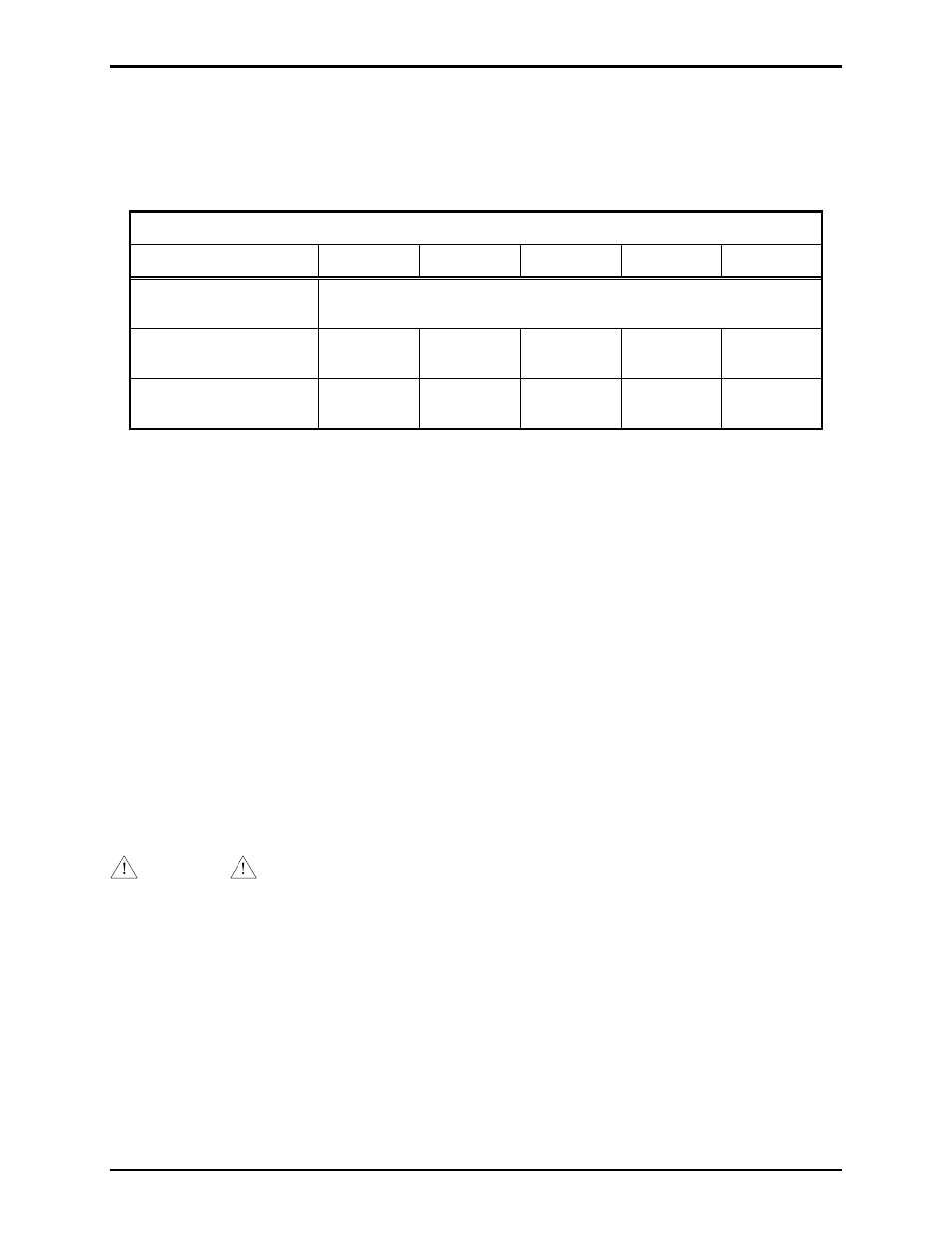
General Wire Types
24
AWG 22
AWG 20
AWG 19
AWG 18
AWG
Maximum capacitance,
C (picofarads/mile)
316,800 pF/mile
Maximum resistance,
R (ohms/mile)
271 171 107 85 67
*Ring signal loss,
decibels (dB/mile)
-16 -12 -8 -6 -4
*Nominal ring signal is 98 dB @ 10 feet.
Installing the Model 262-001 Indoor Telephone
The Model 262-001 Indoor Telephone is intrinsically safe when connected in accordance with
GAI-Tronics drawing 73242 (Pub. 42004-380).
1. Carefully loosen the four front panel screws, and slowly remove the front panel assembly.
2. After the front panel is disconnected, put it aside, and mount the enclosure to the wall using four ¼-20
machine screws with nuts and washers or #14 wood screws of the appropriate length depending on
the mounting surface. Refer to drawing 73242 (Pub. 42004-380) for details.
3. Feed the wire through the hub at the bottom of the enclosure.
4. Refer to drawing 73242 (Pub. 42004-380) for wiring details. The station wire is the pair of wires
coming directly from the GAI-Tronics Model 263-000 Isolation Barrier Unit. This unit must not be
connected directly to the telephone system.
5. Replace the front panel assembly, and tighten the four front panel screws.
WARNING
Substitution of components may impair intrinsic safety.